


James Langham
A Carved Warren : Reorder, Shell + Lining

Follow:


Awards
Skills & Experience
- McLaren.Excell, Part 1 Assistant: April - August 2024
- Amazon Construction LTD, Carpenter & Labourer: Feburary - April 2024
- GSS Architecture: June - August 2024
Project description
The Reordering of “Block C” of Summerhall Edinburgh is intended to allow for collaboration across university, apprenticeship and technical colleges by providing a series of making, working, exhibition and discussion spaces. The ground floor of the building contains various sizes of internal & external workshops intended for heavier, “dirtier” work, with the surrounding buildings being used for storage of material and a semi public courtyard for ease of transportation and material delivery. The first floor contains a series of “clean” discussion and studio spaces, alongside an exhibition wing. The connection of the 2 is emphasised by cutting the existing floor to form internal light wells. The tower sat adjacent to the building is reconfigured to contain accommodation for those who are external to the university use the facility.
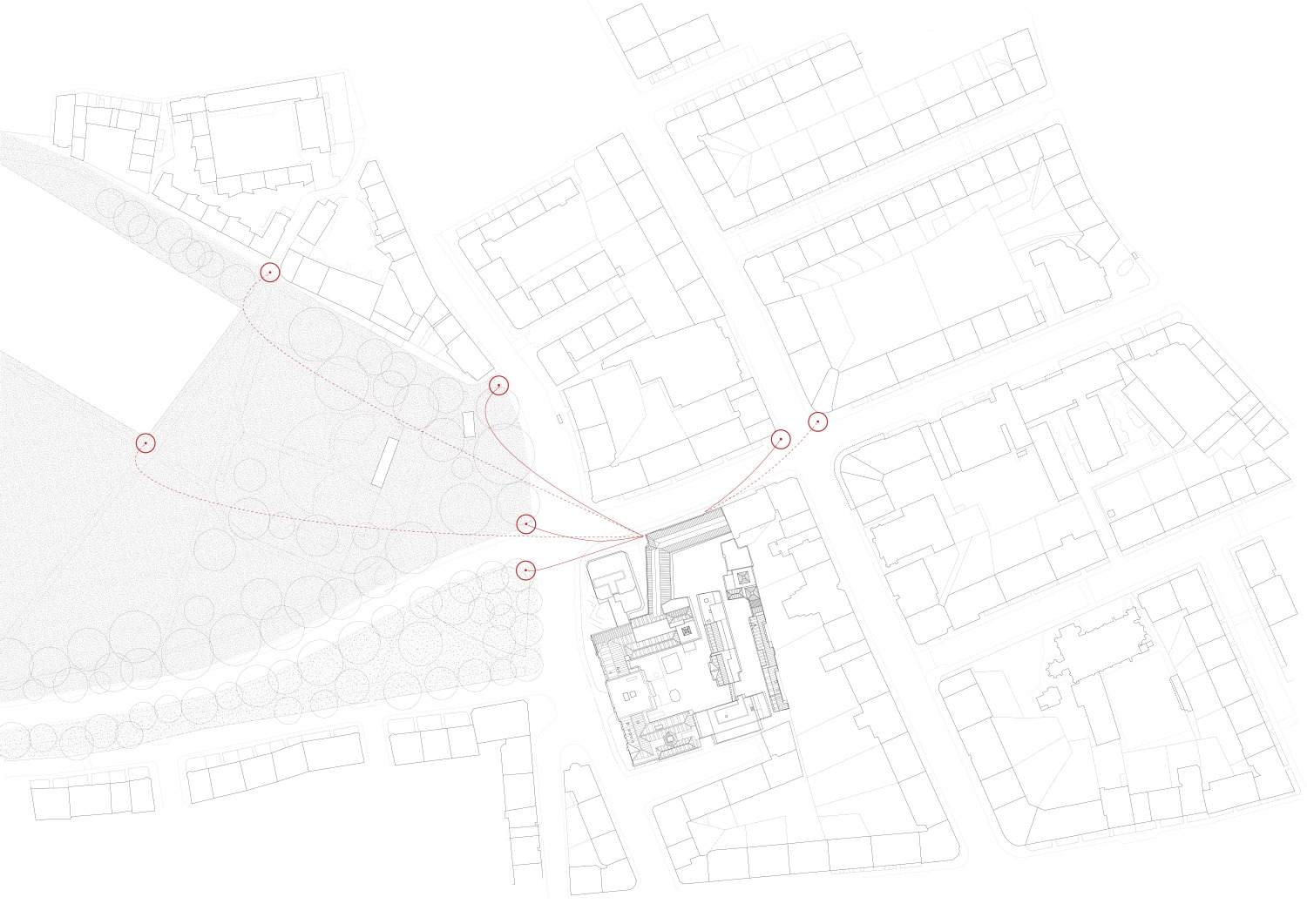
The civic presence of the building is re-orded by defining a new street entrance and public courtyard which leads users into the building. By removing the existing railings and engaging the space between itself and adjacent tower the building is opened up physically and visually.
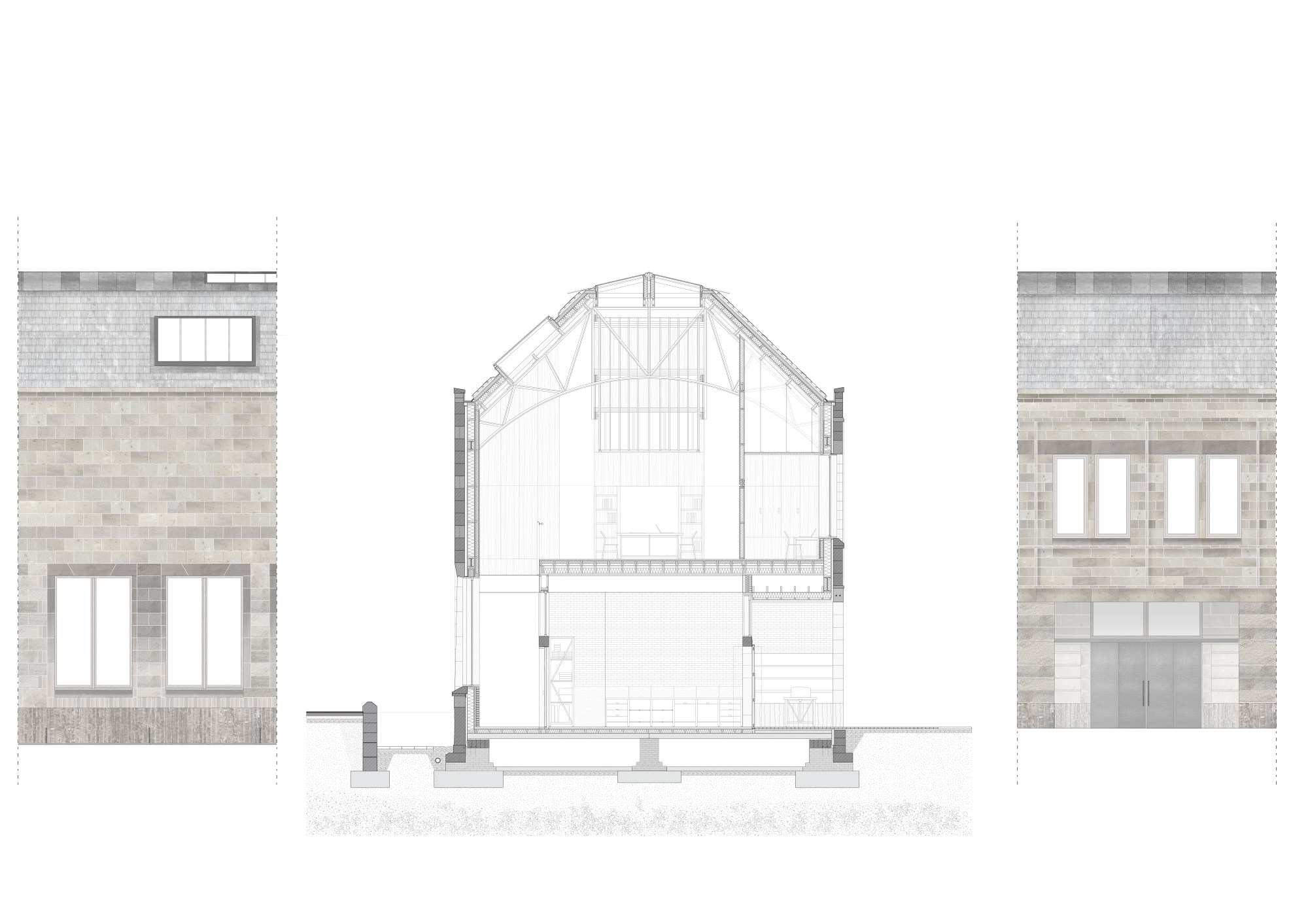
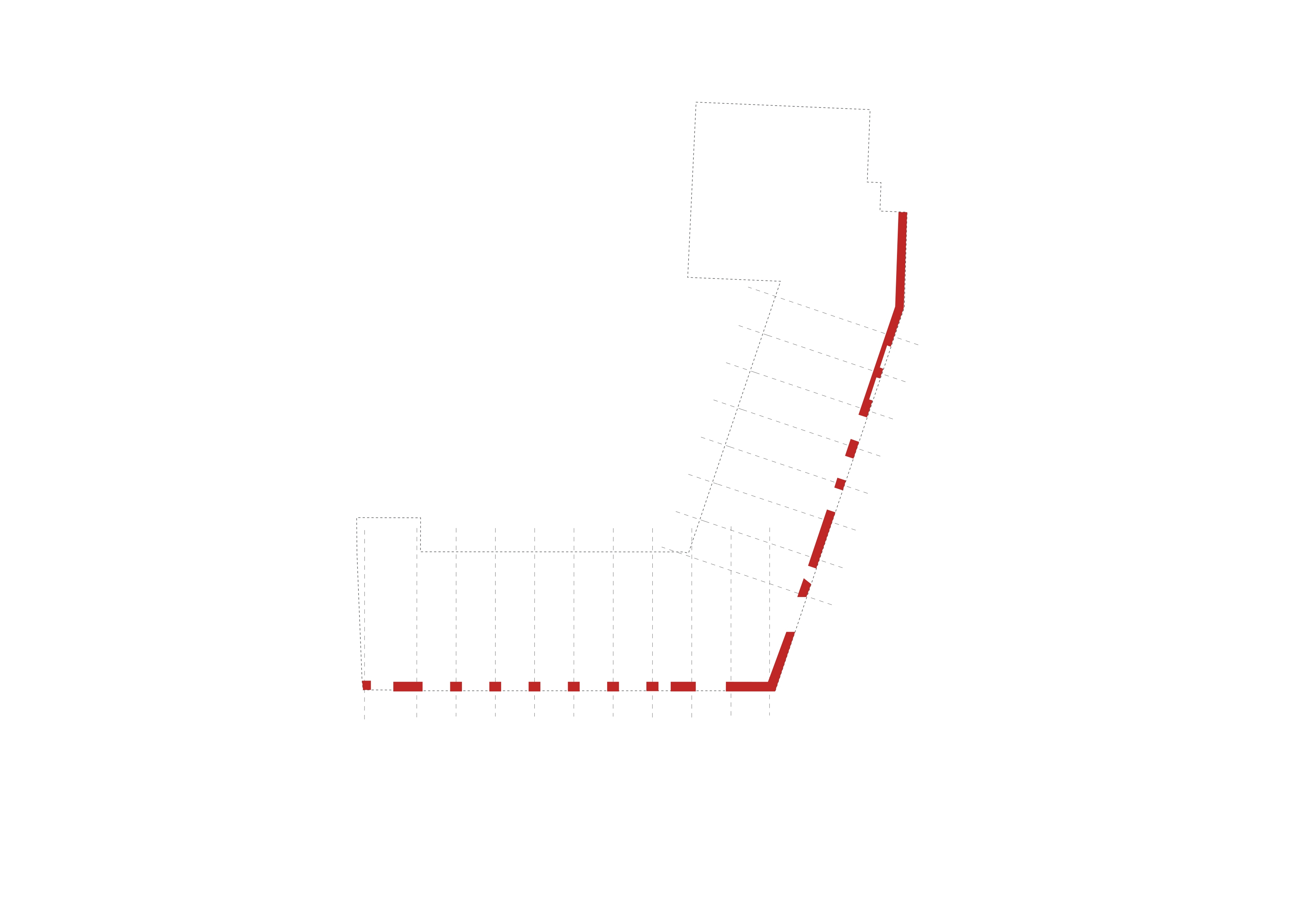
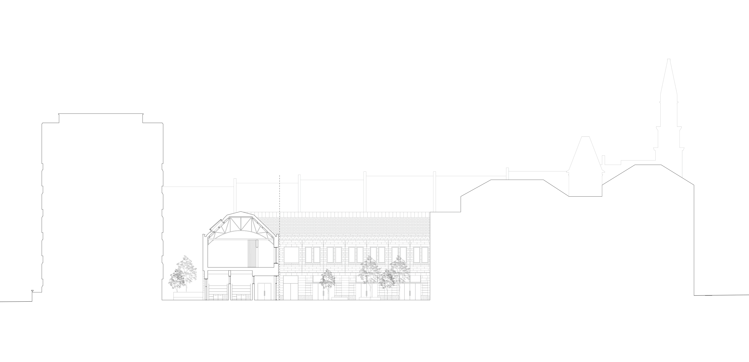
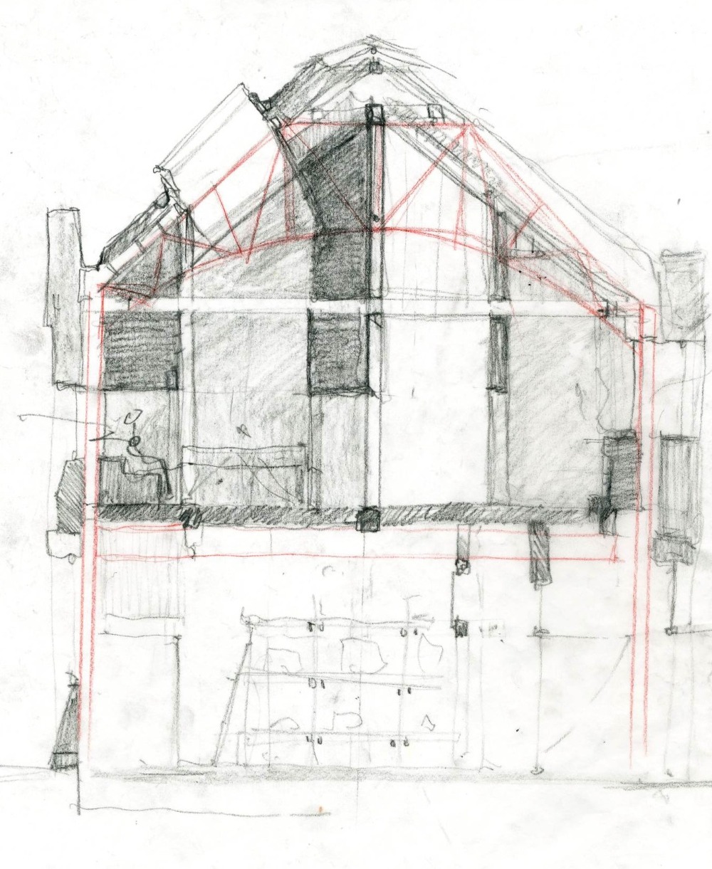
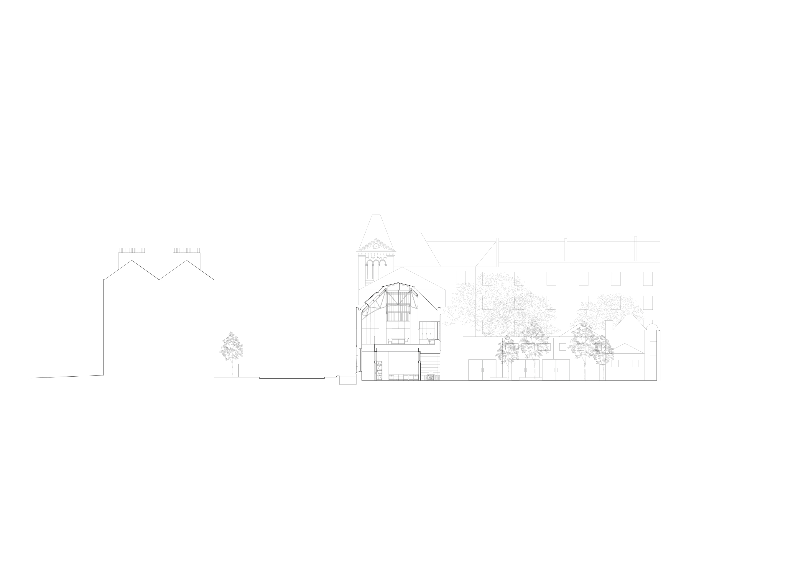
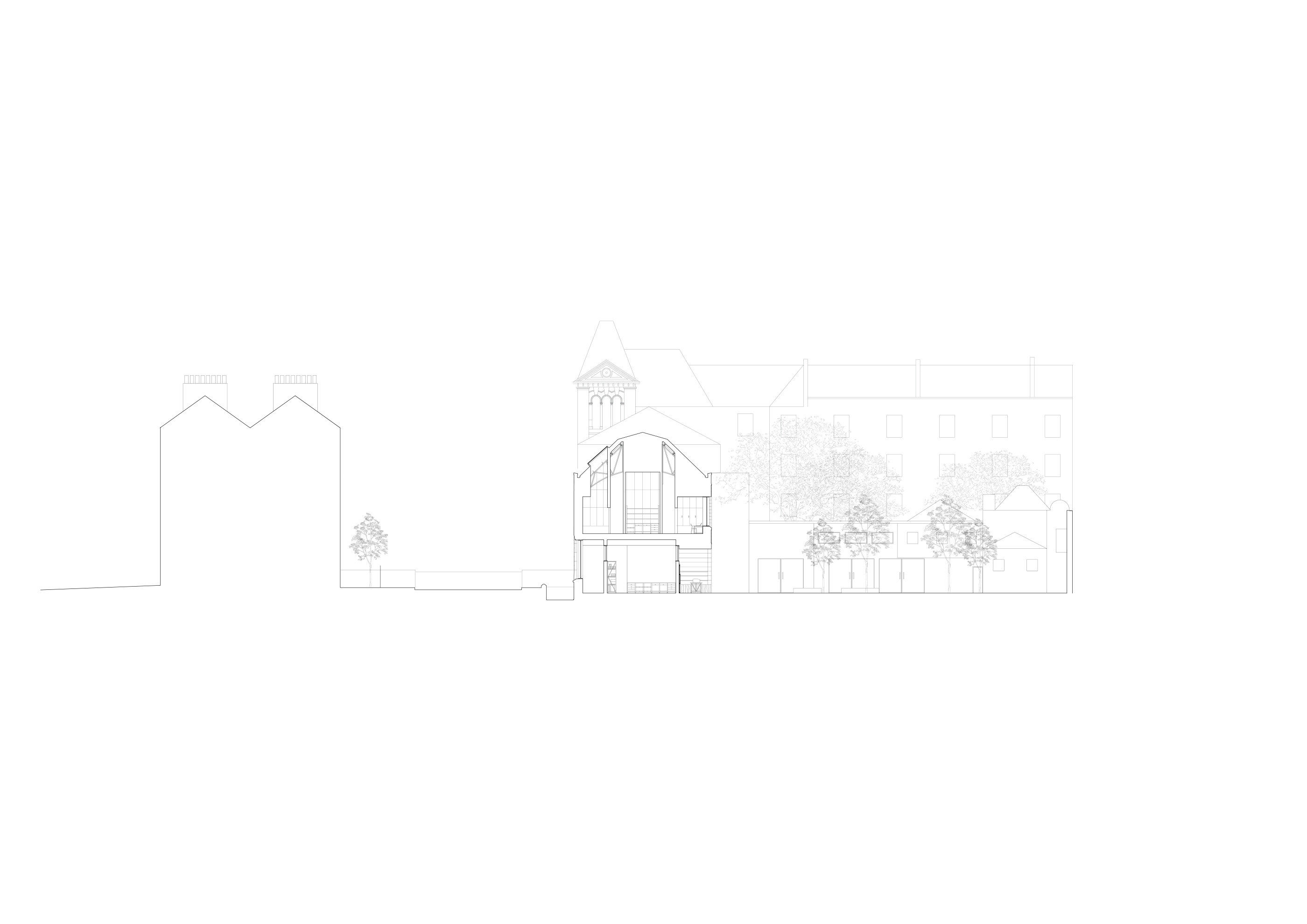
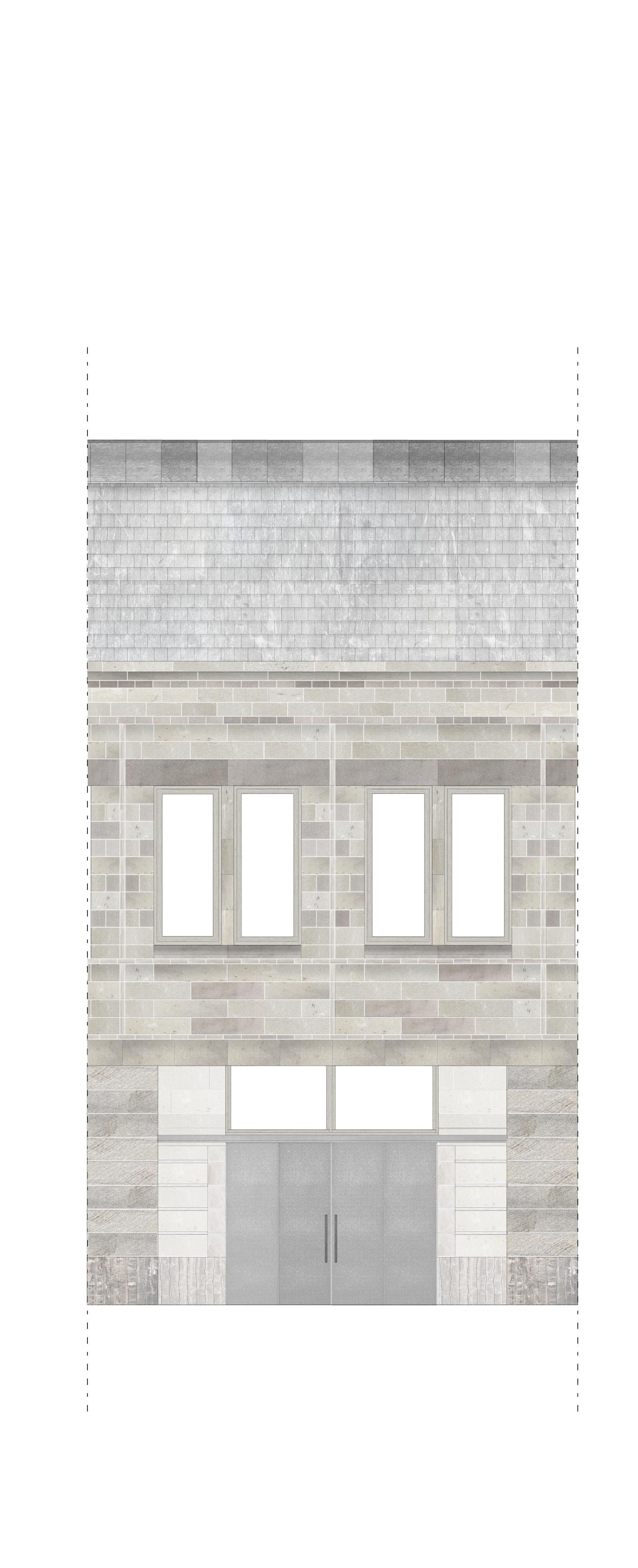
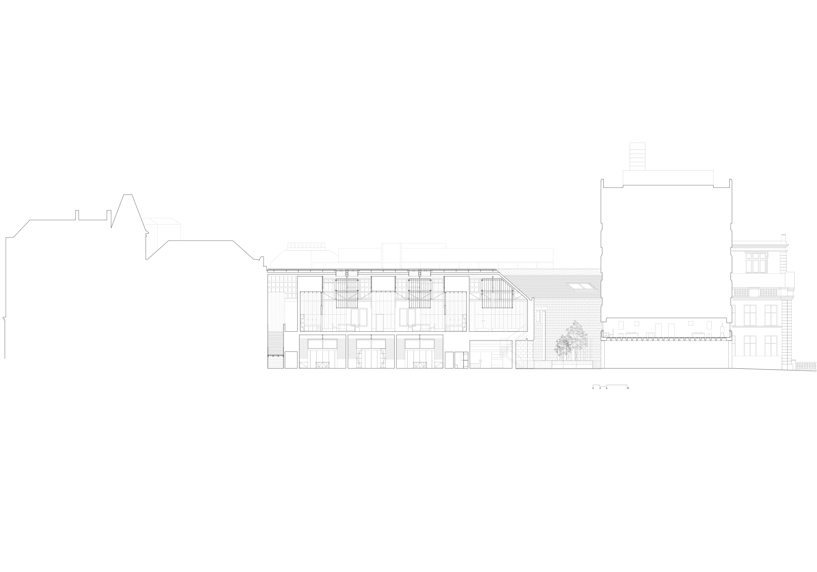
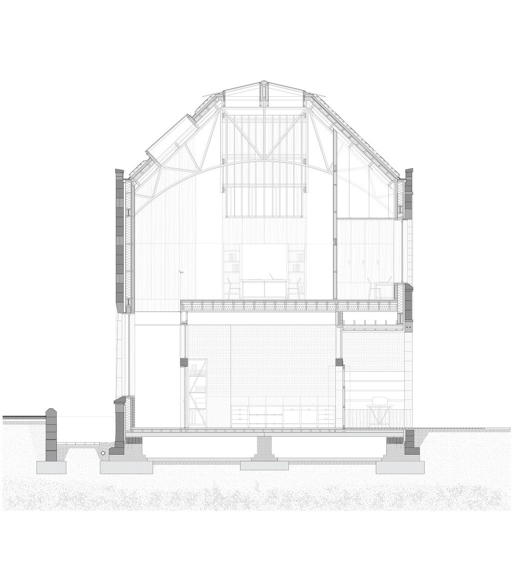
1:50 Technical Section + corresponding Elevations
Host - Summerhall, Edinburgh
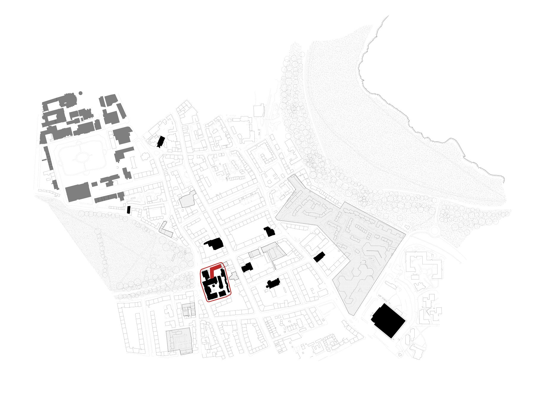
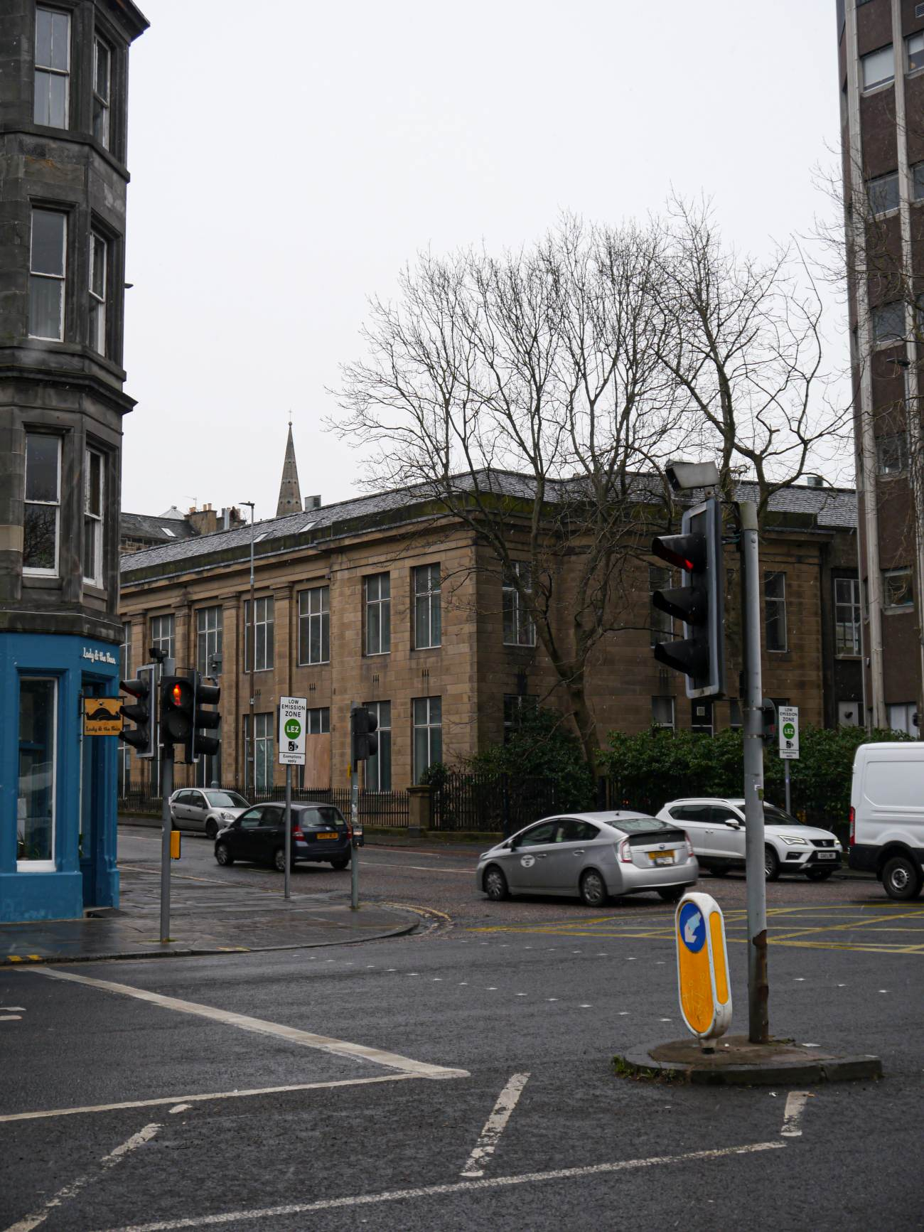
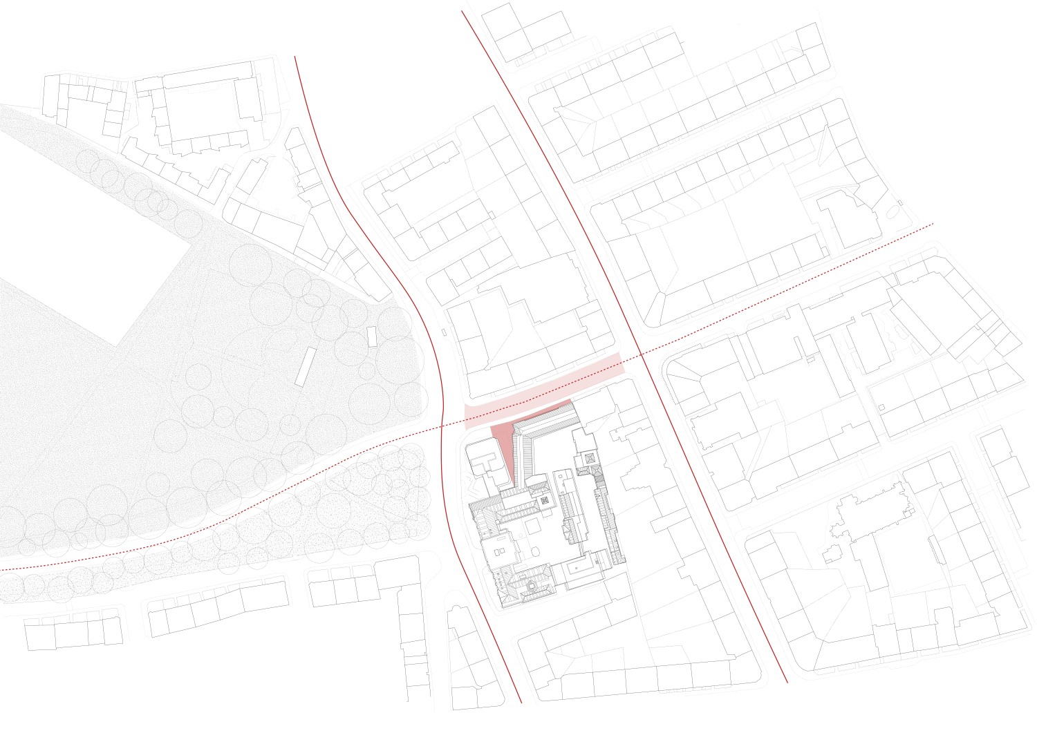
Summerhall, located on the south east corner of the Meadows, Edinburgh, currently resides as an arts centre, comprising of several independent businesses and studios. Containing 6 principle building zones and 2 courtyards, summerhall contains layers of urban fabric from the late 1800’s, mid 1900’s and, the latest of these developments, found in the 1980’s. The main building, distinctive of its classically ordered facade, was constructed to be house Edinburgh Universities veterinary school , with the subsequently build buildings of block B,C and D, added to accommodate further laboratories. Contextually, the site is positioned with the potential to engage more with the city than at present. Historically, the northern elevation of the site confronted this, containing shop fronts and 2 churches, only one of which still remains. The surrounding community of Newington is historically one of industry, once containing engineering works, train depots and printmakers. Hence, in reading the site as a whole, connecting the surrounding contexts historical significance and present city engagement, is fundamental in developing a specific attitude to reorder.

1:5000 Location Plan

Historical Growth of Summerhall - Buildings

Historical Growth of Summerhall - Plans
On Site Analysis
1:2500 Generative Analysis

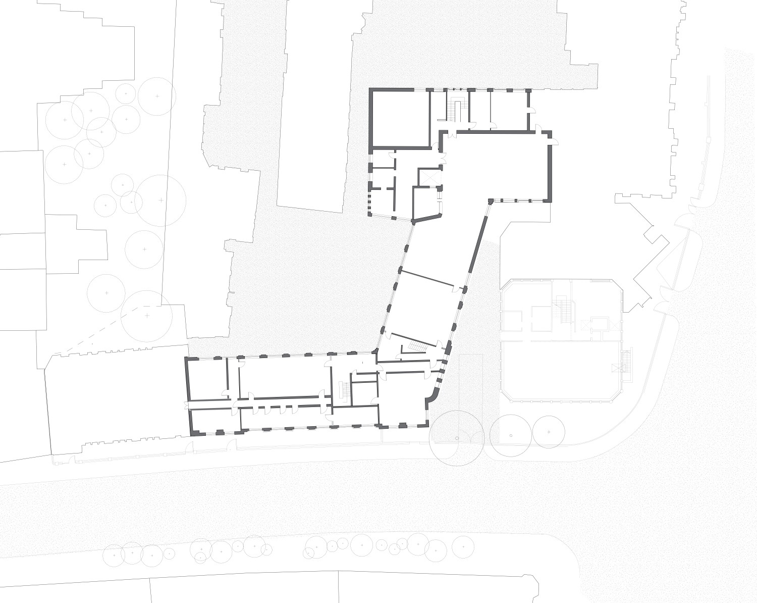
1:500 Existing Site Plan
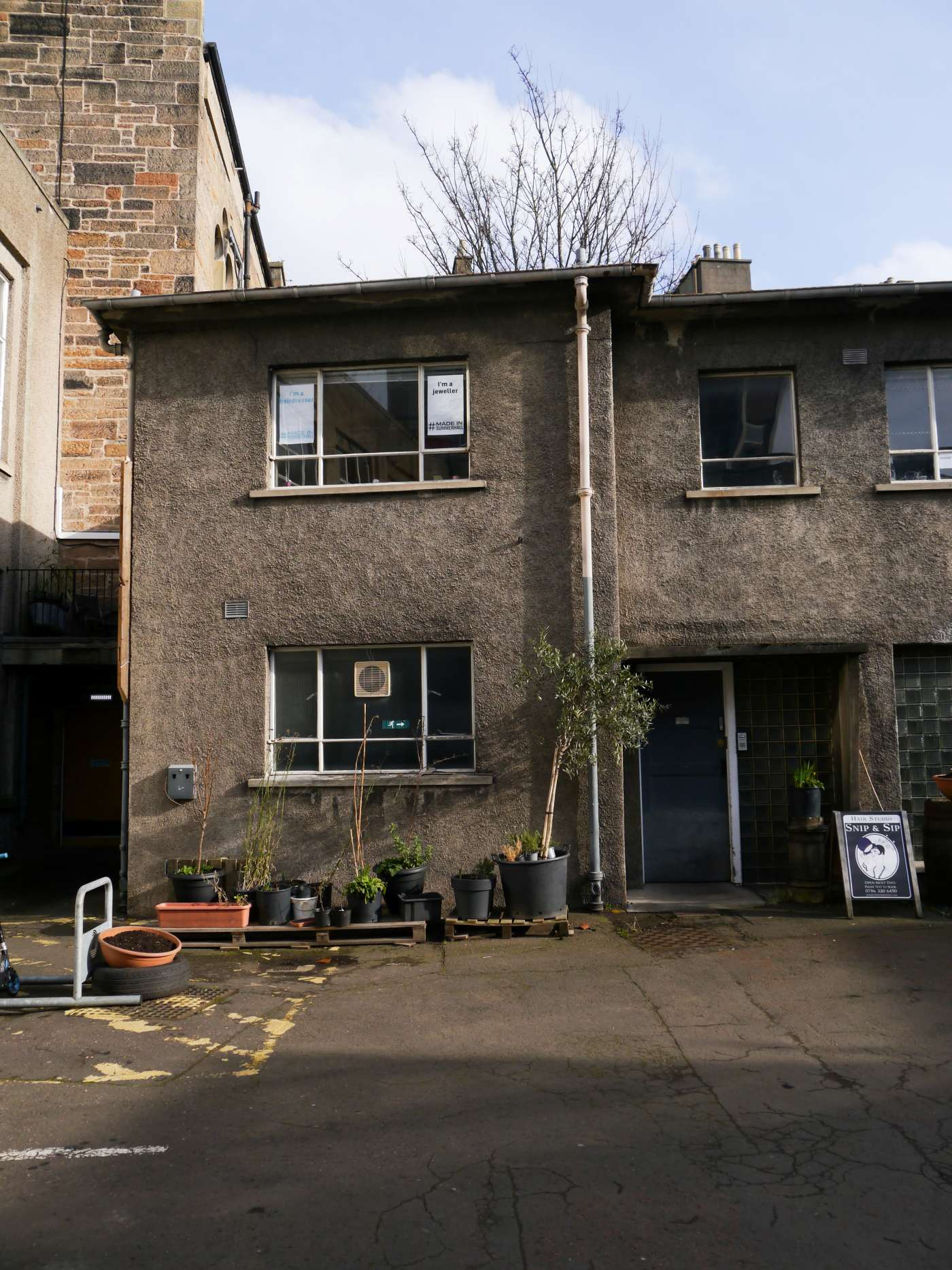
1:500 Existing Approach to Block C
1:500 Existing Relation to Street

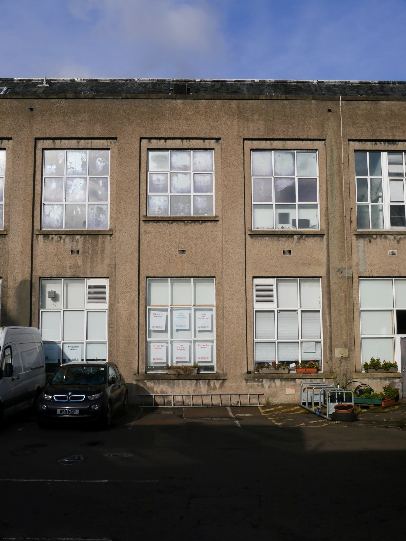
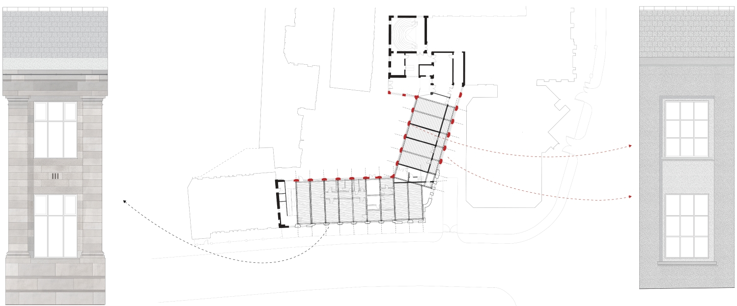
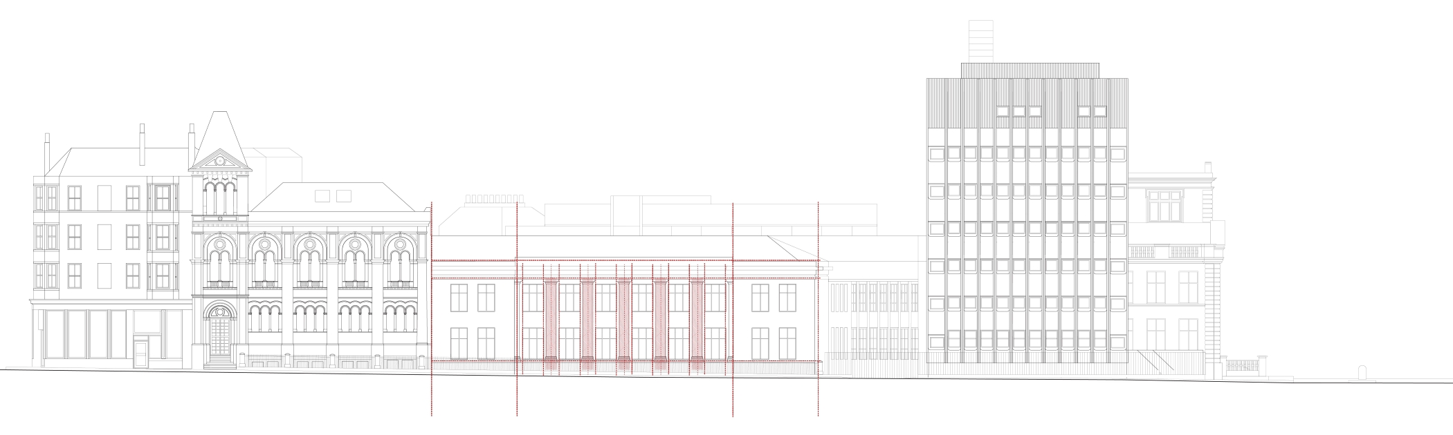
Existing West Elevation of Summerhall Campus
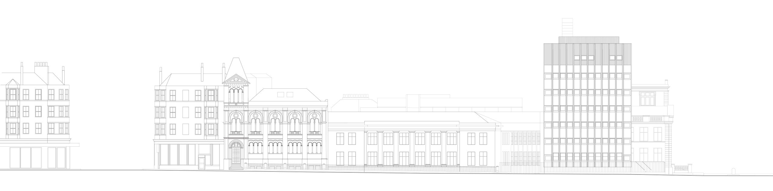
Existing North Elevation
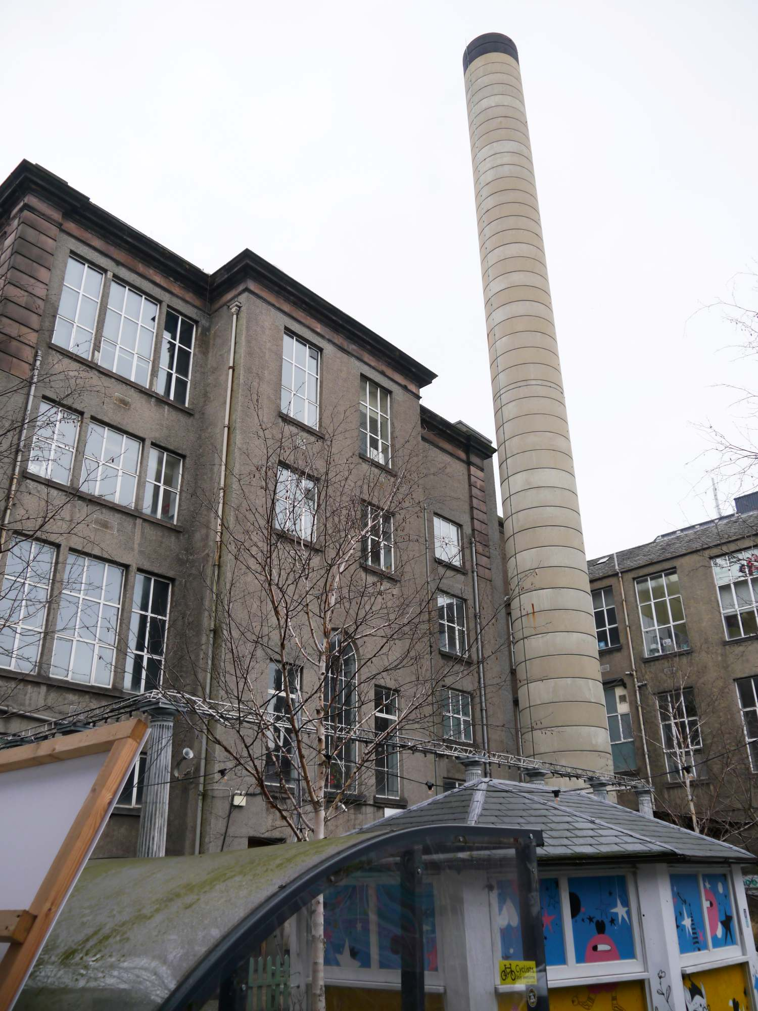
Block C
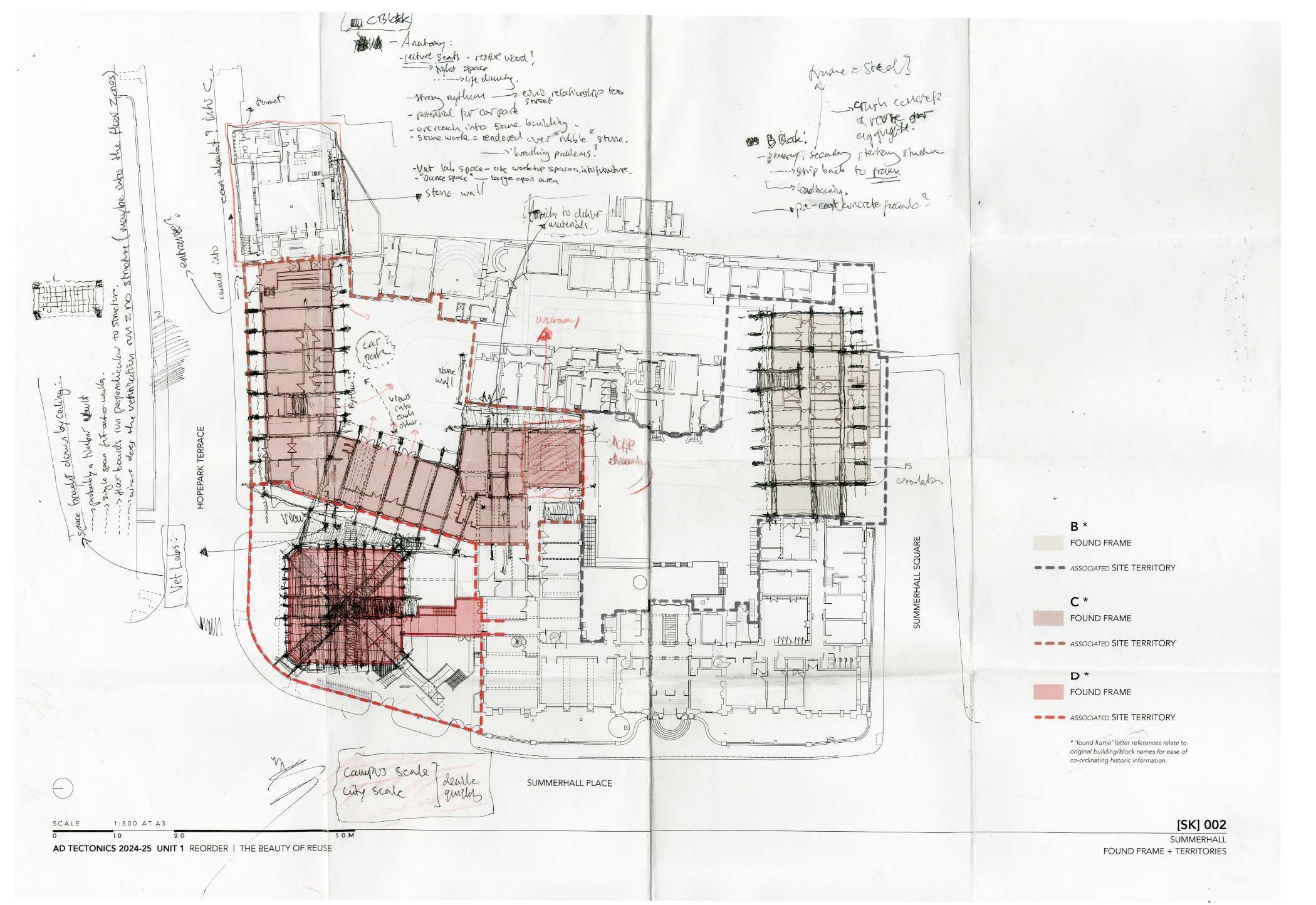
The building being reordered in this case, named “Block C”, designed by Lorimor and Matthew in the mid 1930’s, was once dedicated to anatomy research and dissection. Having a key “street” presence, currently underused as a result of its existing programmatic layout, presence an opportunity to engage the campus more actively on its north face. The cranked geometry, a result of a pre-existing church which resided where block D now sits, provides a pivot between its 2 wings. This hinge point provided apt physical and visual connection to its entrance. The following analysis indicates the key parameters and “fragments” taken from the buildings existing condition, and chosen to associate itself with the given programme of making, exhibiting and learning.
On Site Analysis
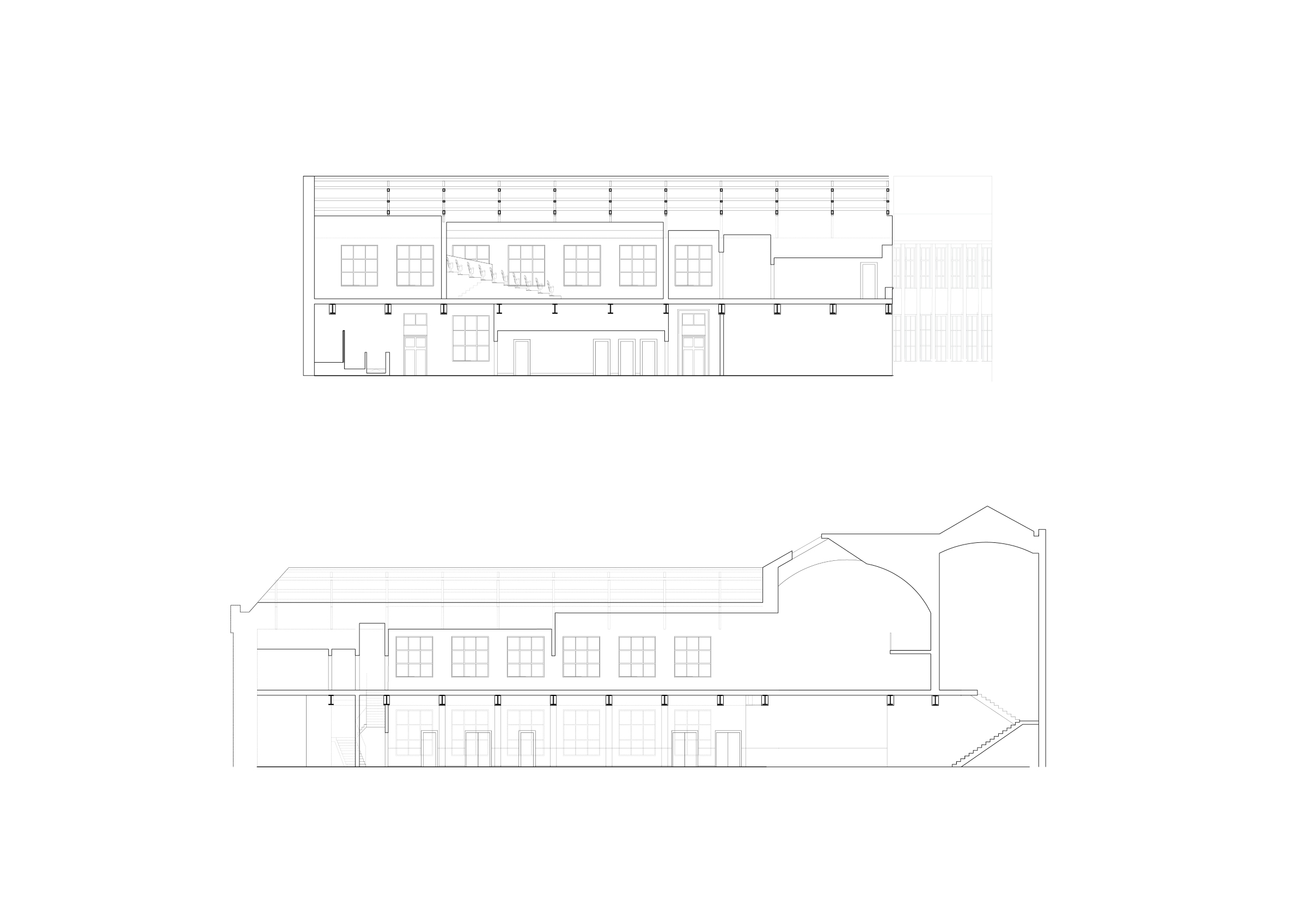
1:200 Existing Sections

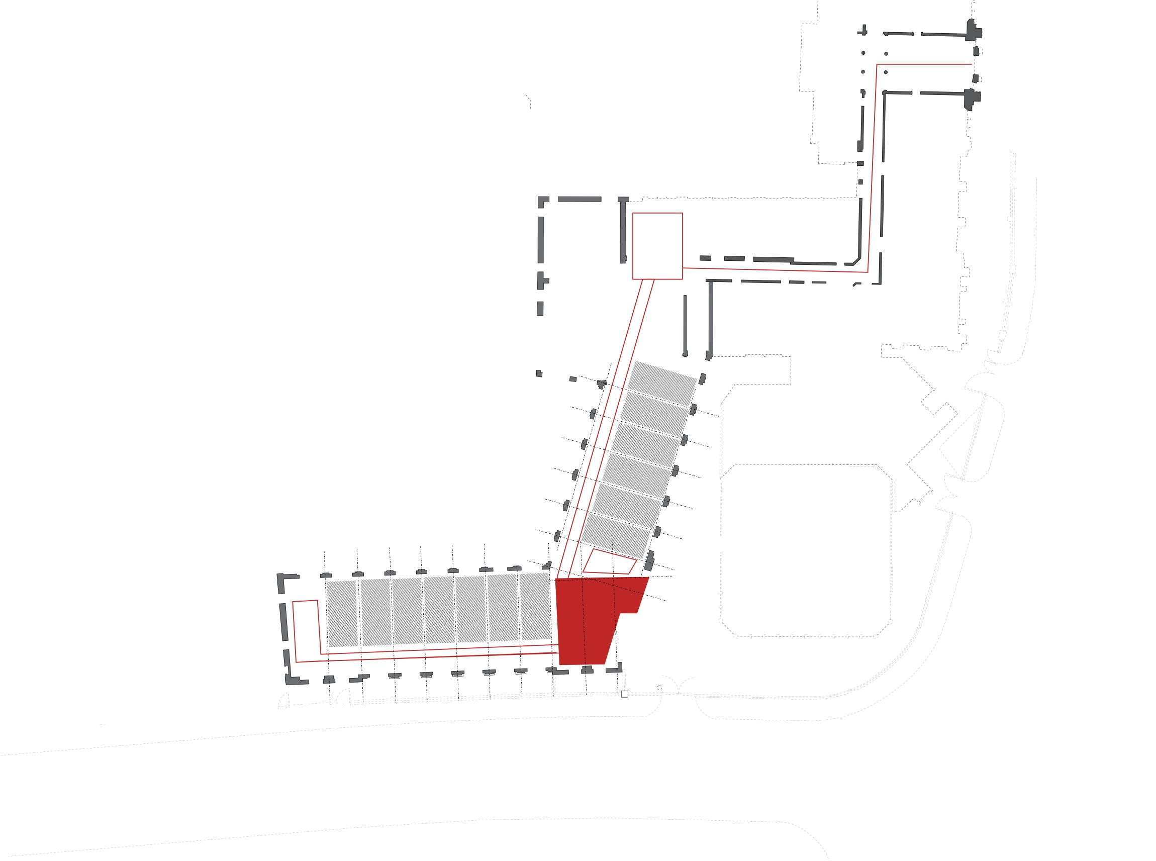
Block C - Existing Access

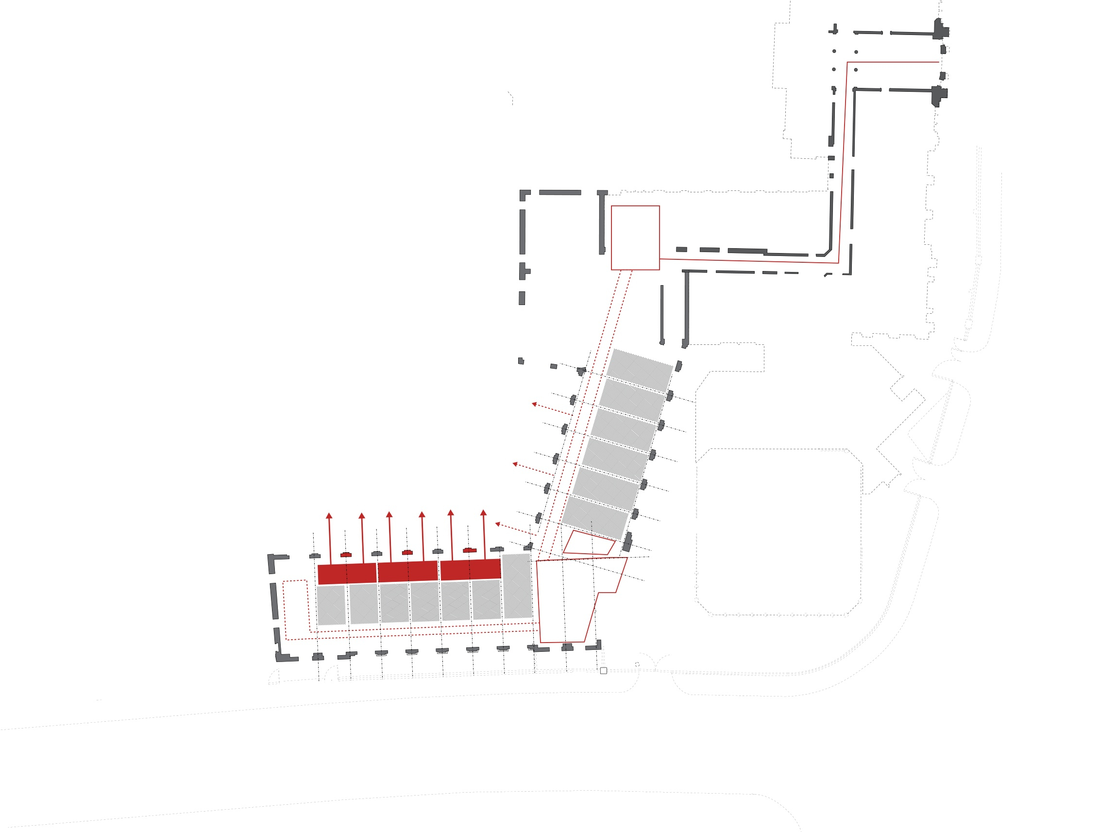
Block C - Proposed Access Points

Key Civic conditions to exploit - Street Facing Facade + Courtyards

1:200 Existing Ground Floor
1:200 Existing 1st Floor
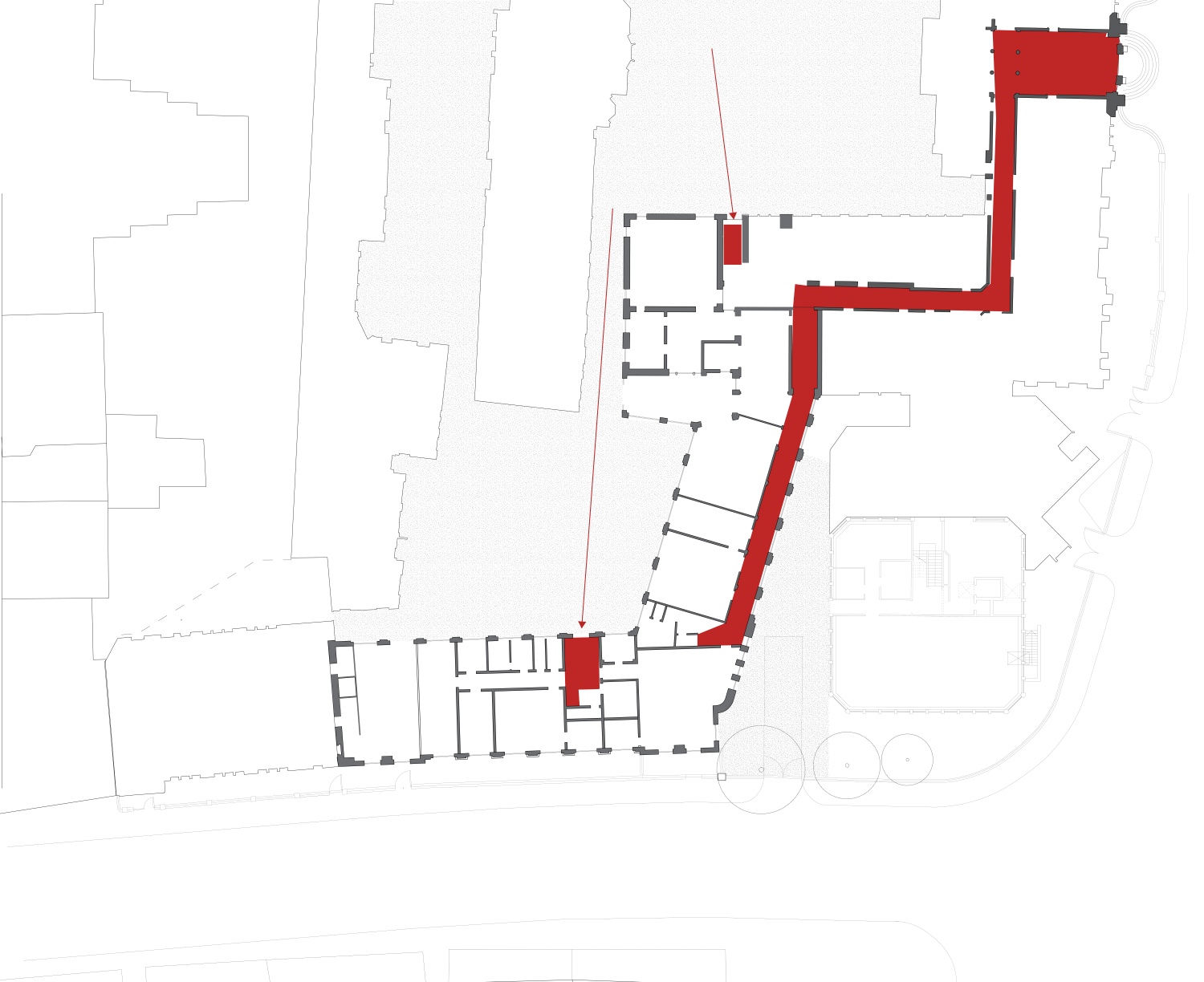
Existing Access + Circulation
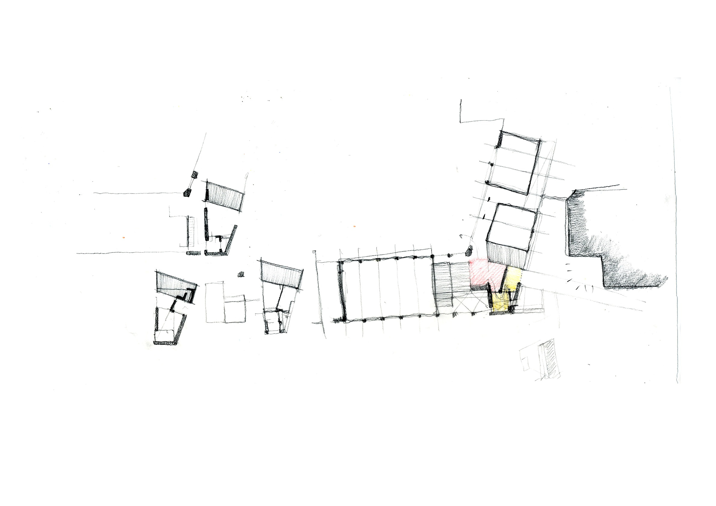
Programmatic Reordering
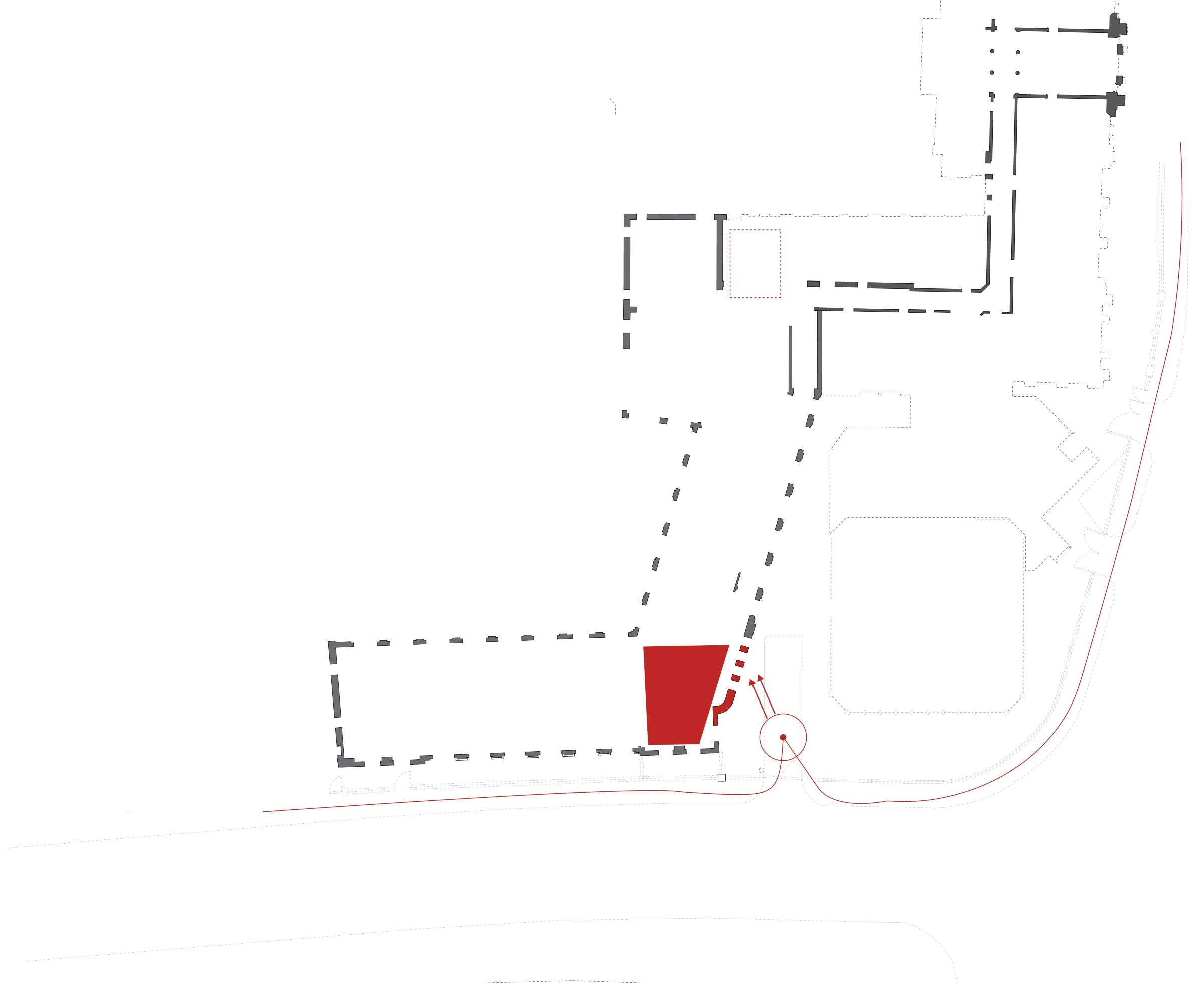
Proposed Entrance
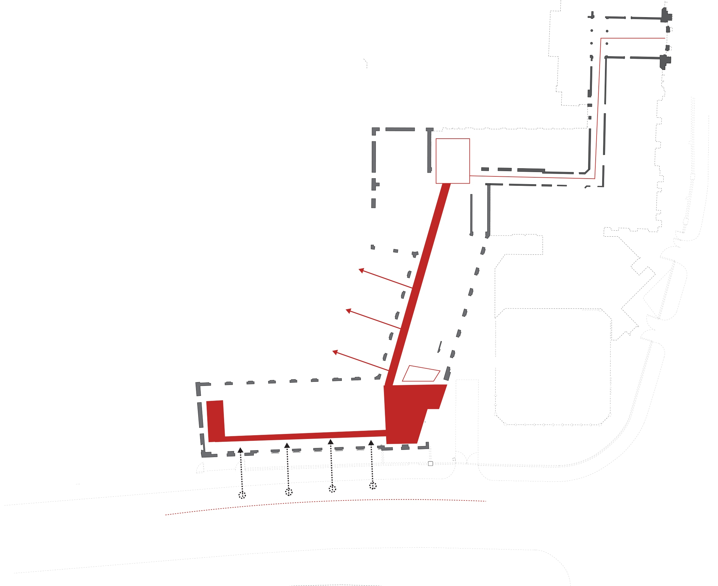
Proposed Circulation
Proposed Entrance + Internal volumes
Proposed external working zone
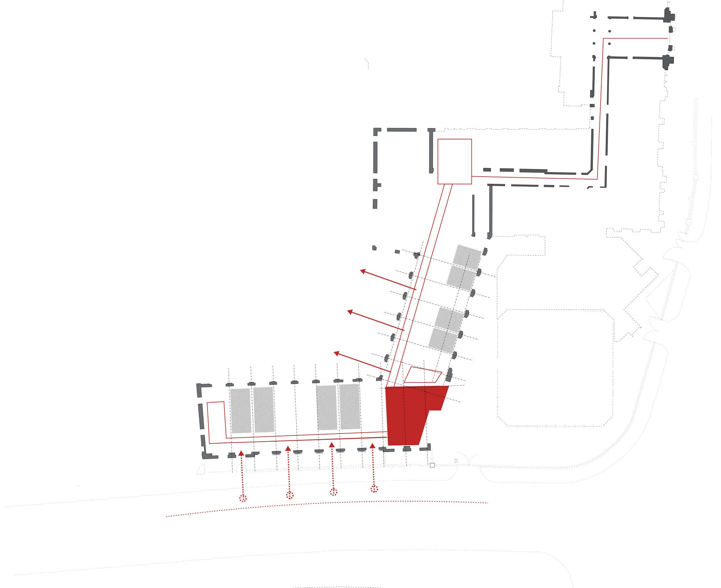
Proposed Visual + Physical connection to external spaces
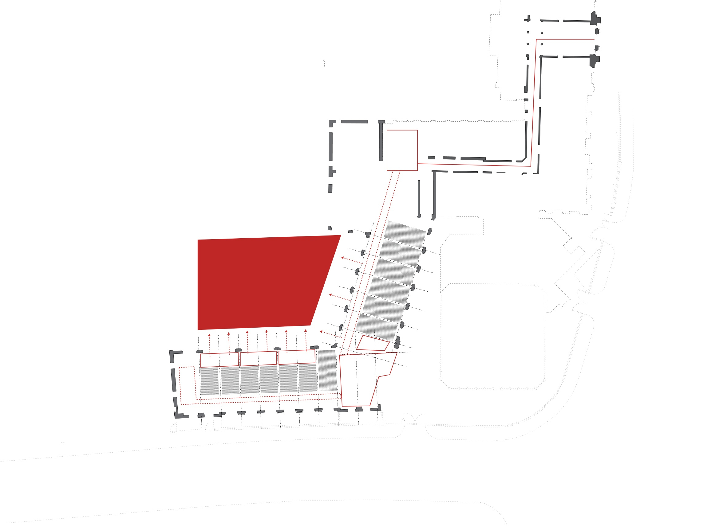
Proposed revitalisation of Courtyard

Proposed addition of Entrance Courtyard
Existing Tectonic
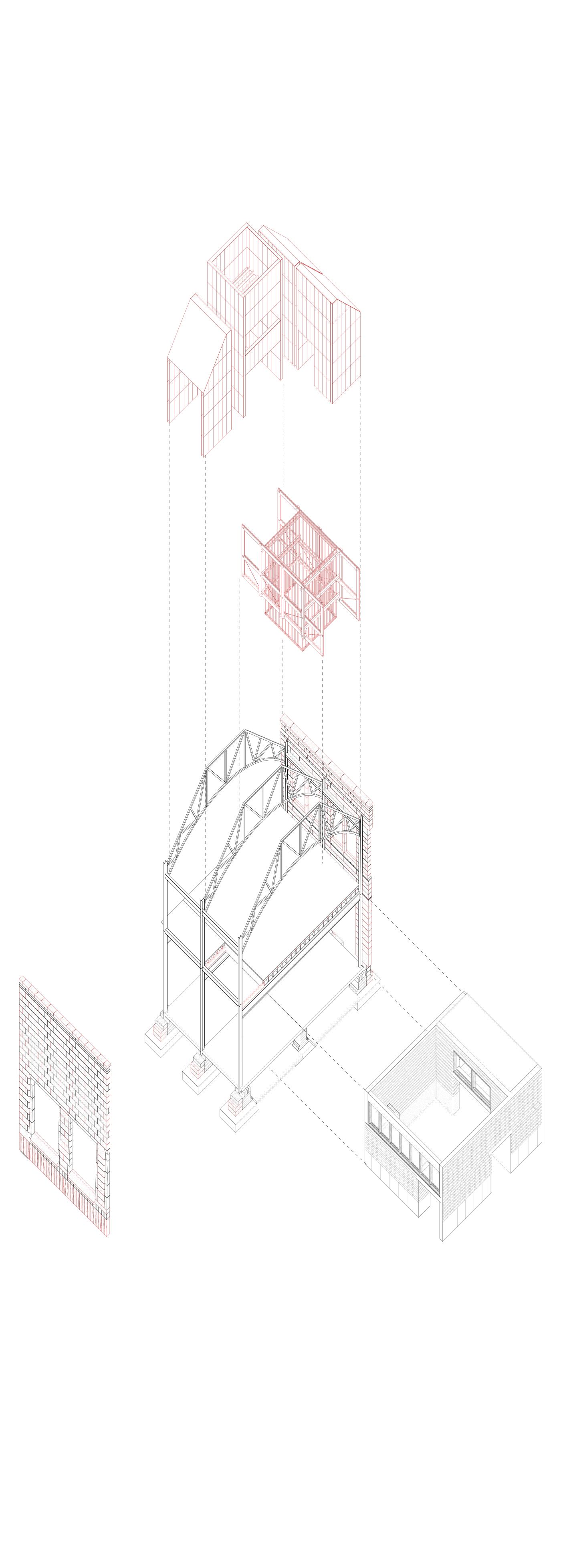
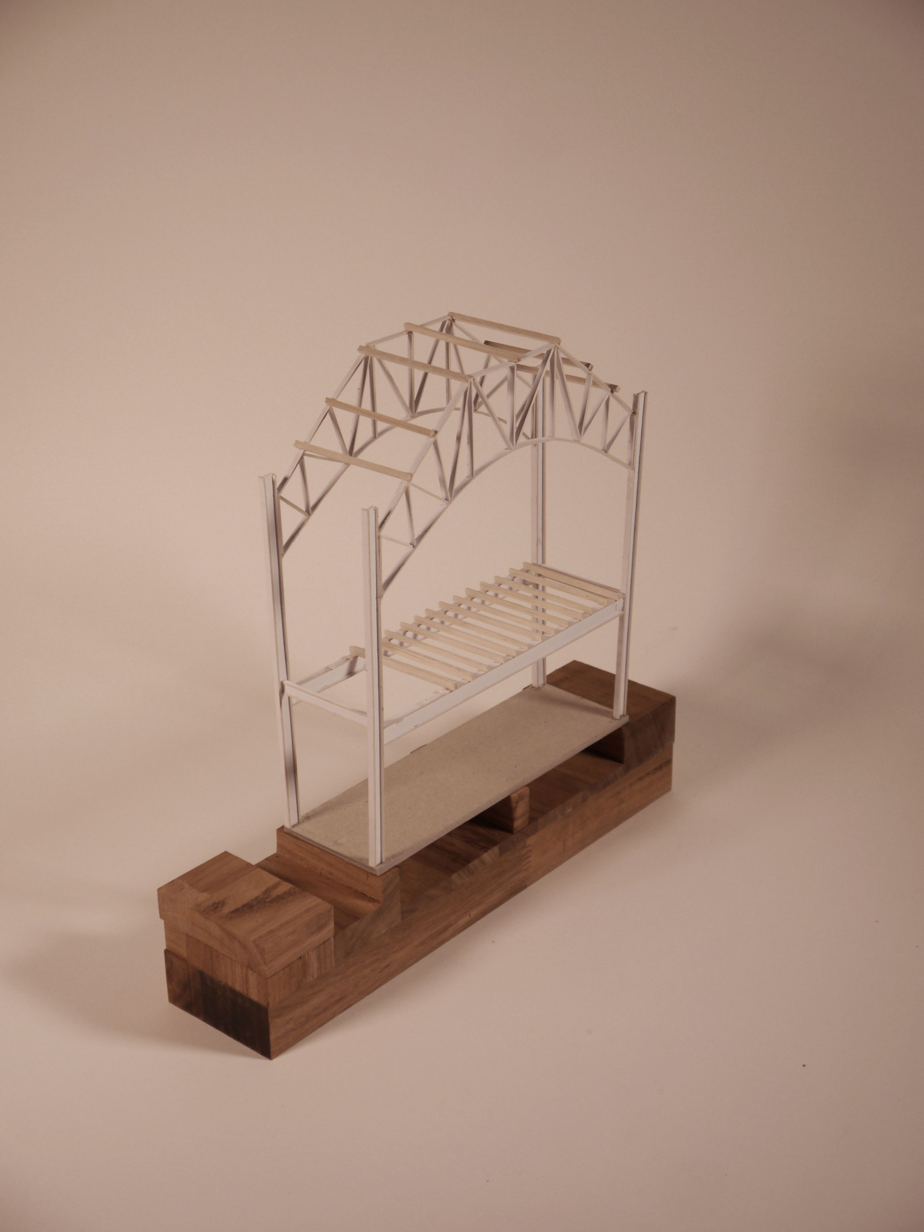
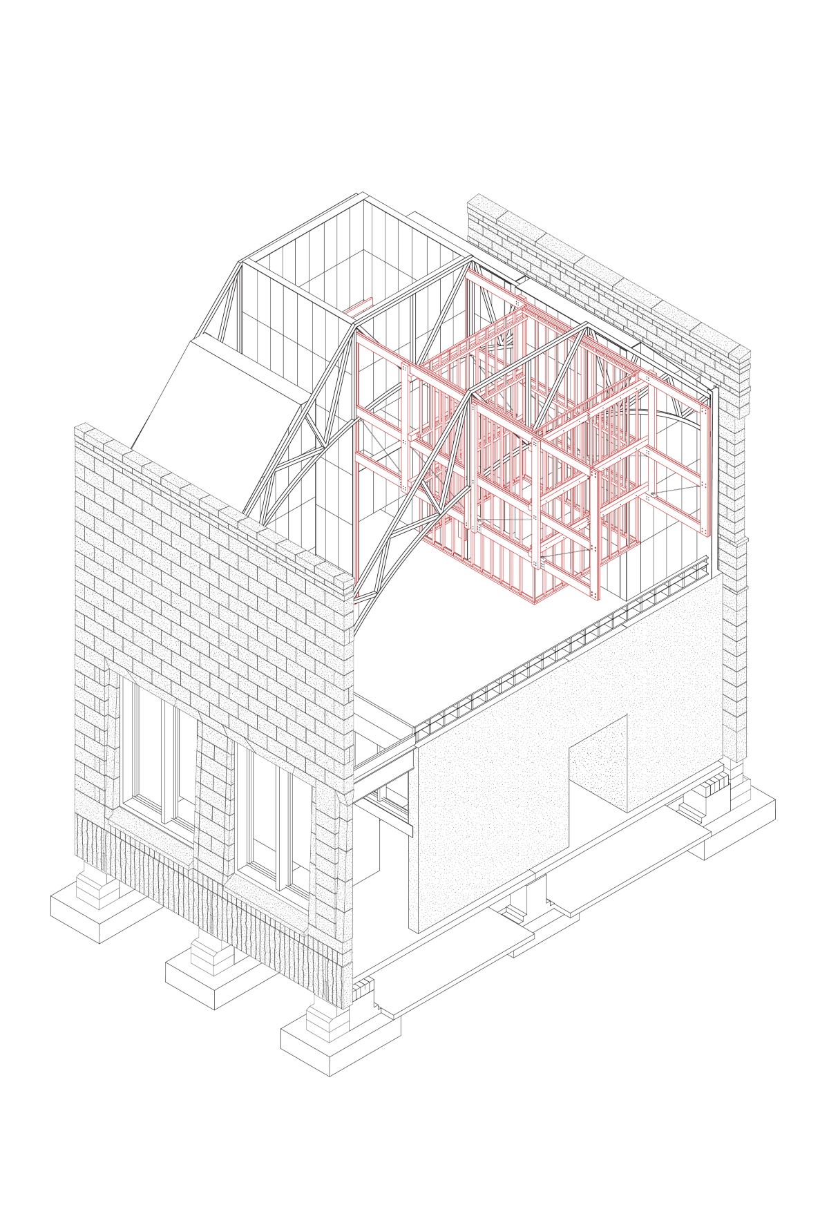
The existing structure is comprised of a load bearing steel frame, made characterful by the distinct steel trusses spanning the 11m depth of the building. A double leaf brick infill is used to form the buildings shell, with the street facing facade lined in an ashlar sandstone. In terms of material reuse, the existing frame is reused, with its infill materials being cut & relayed to reorder both the existing programme and aesthetic order.
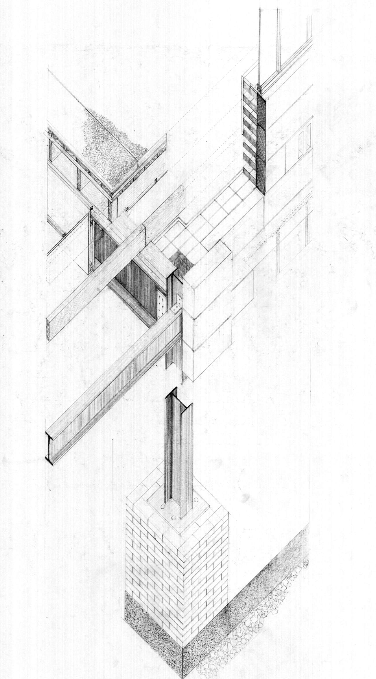
Existing Technical Axonometric - 1:10
Existing Structure
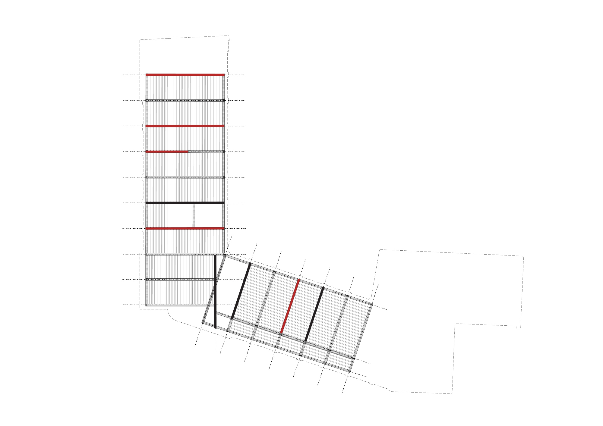
Existing Primary + Secondary Structure
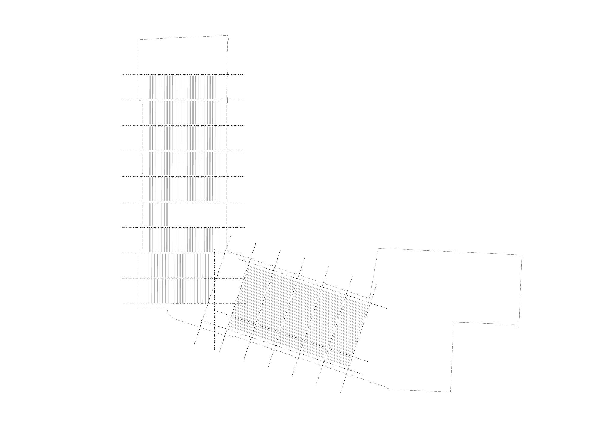
Existing Structure - Floor Joists
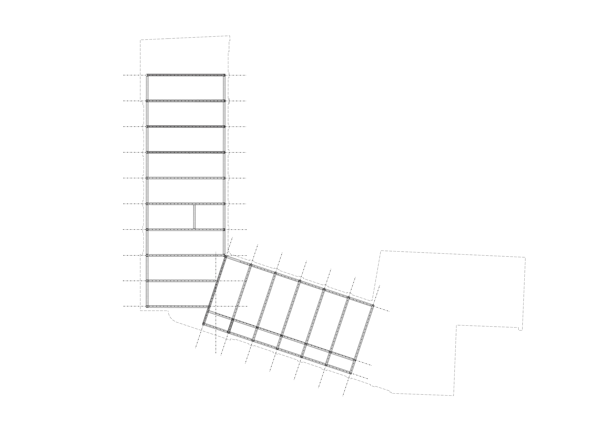
Existing Structure - Steel

Existing Structure - Internal Bracing Walls (Brick)

Block C - Existing Structure
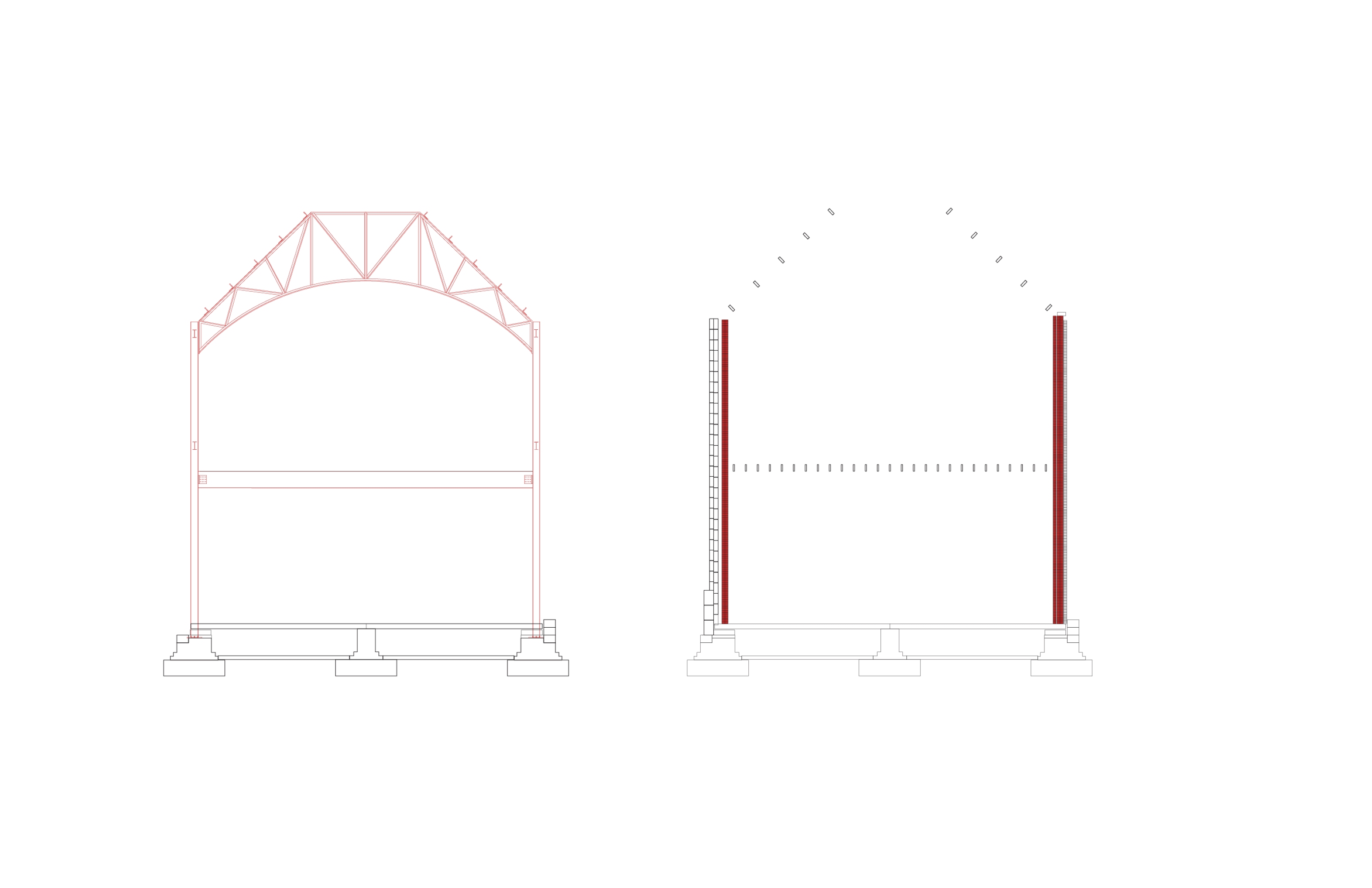
Existing Structure - Steel + Masonry Infill
Material Analysis
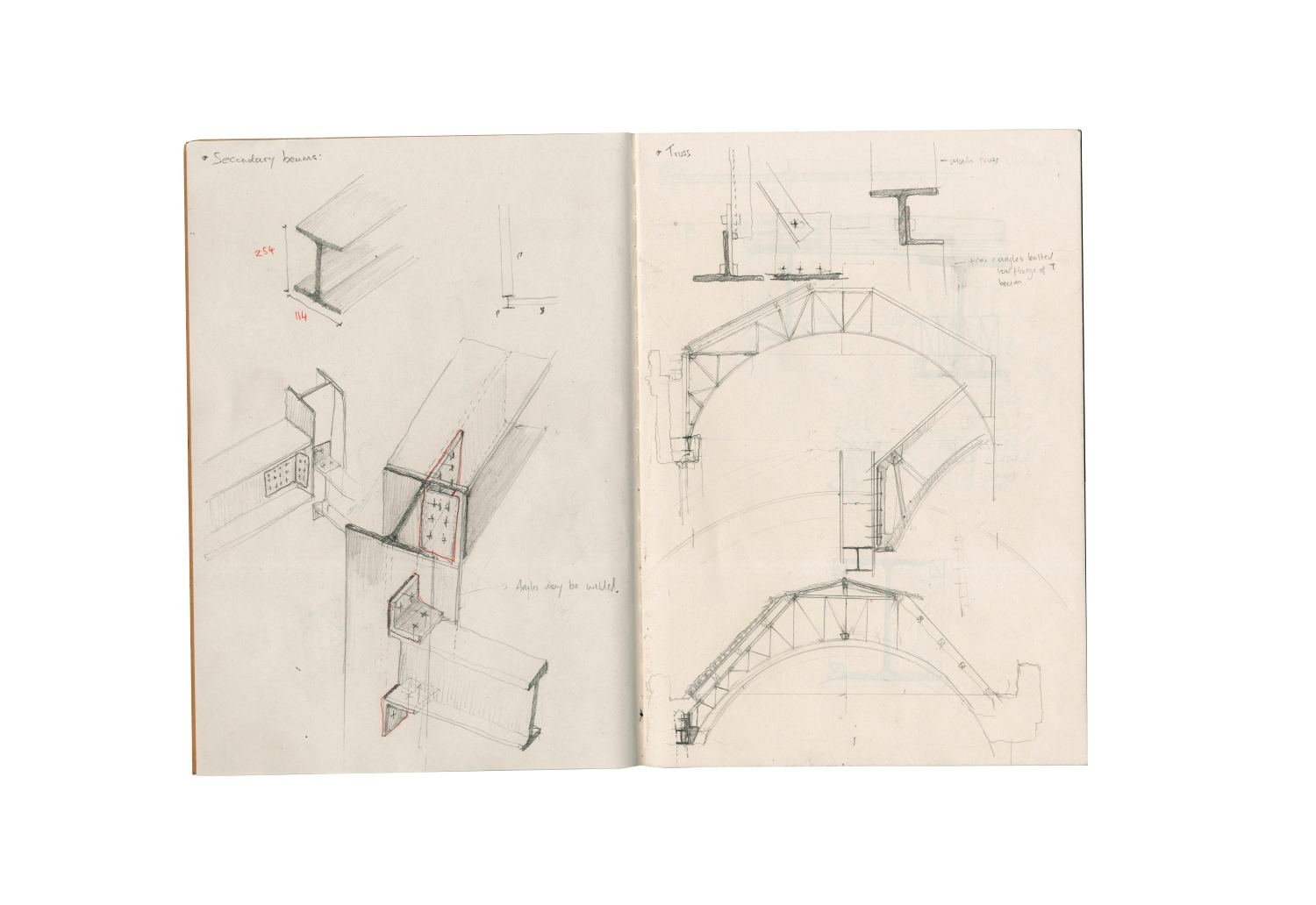
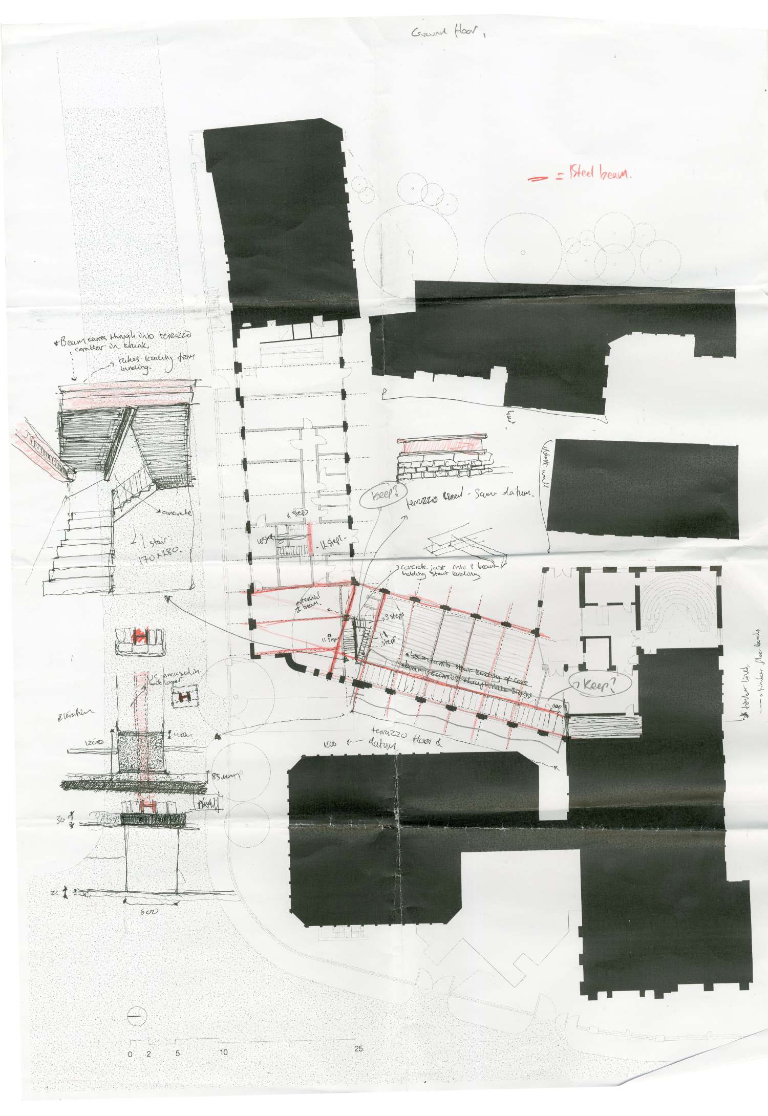
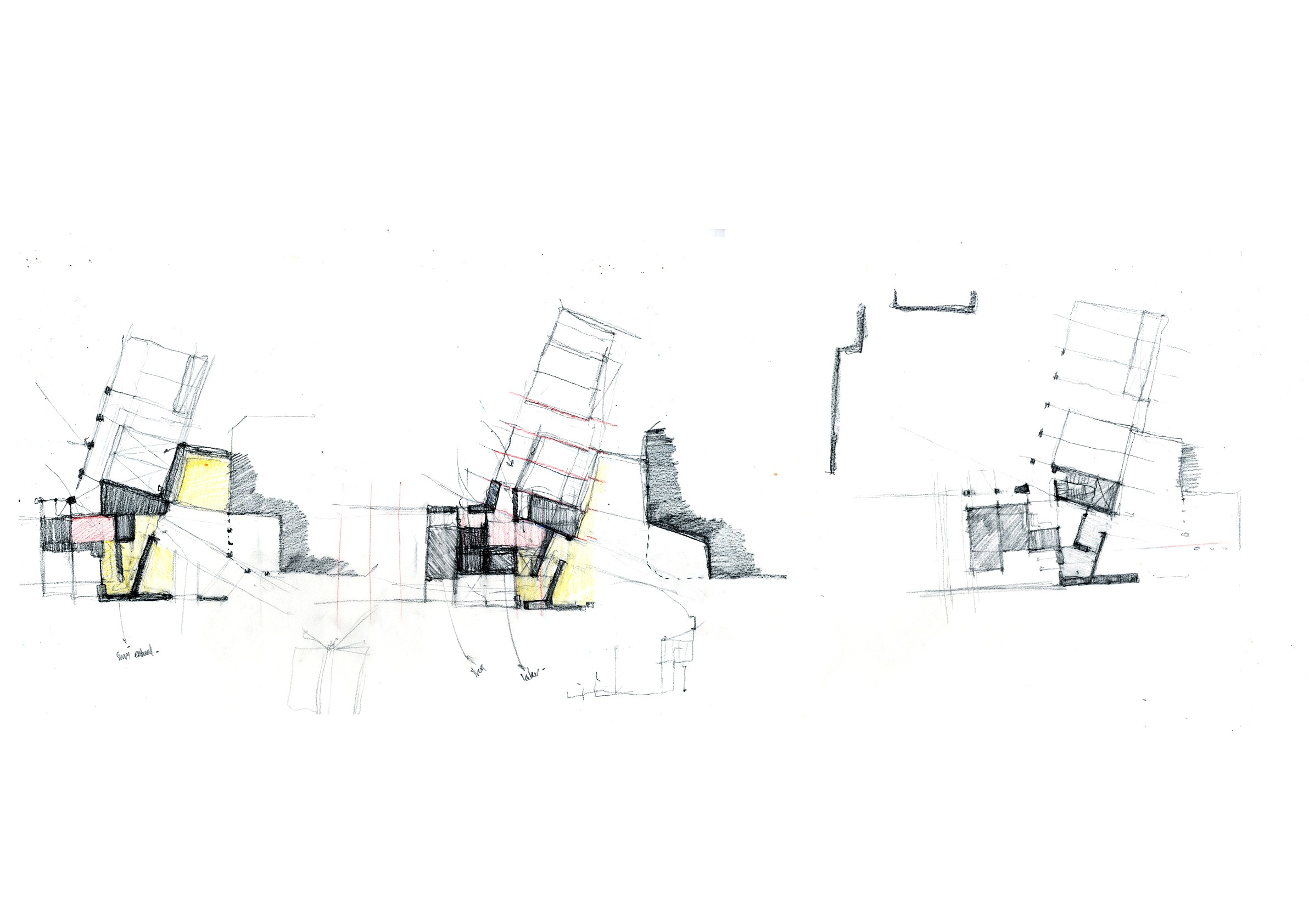
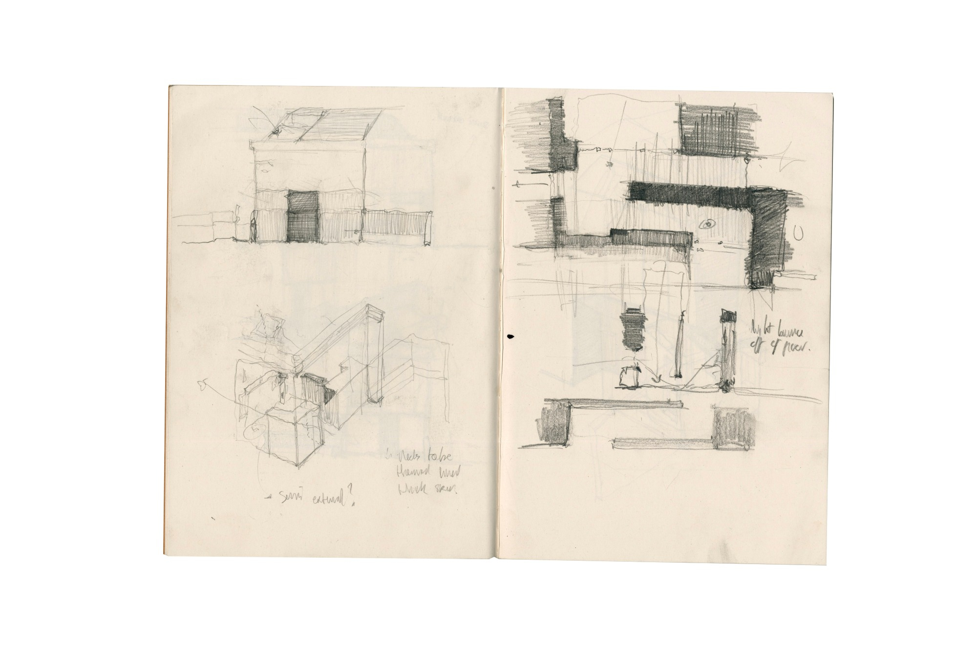
Investigative Sketches of Existing Tectonic
Proposal
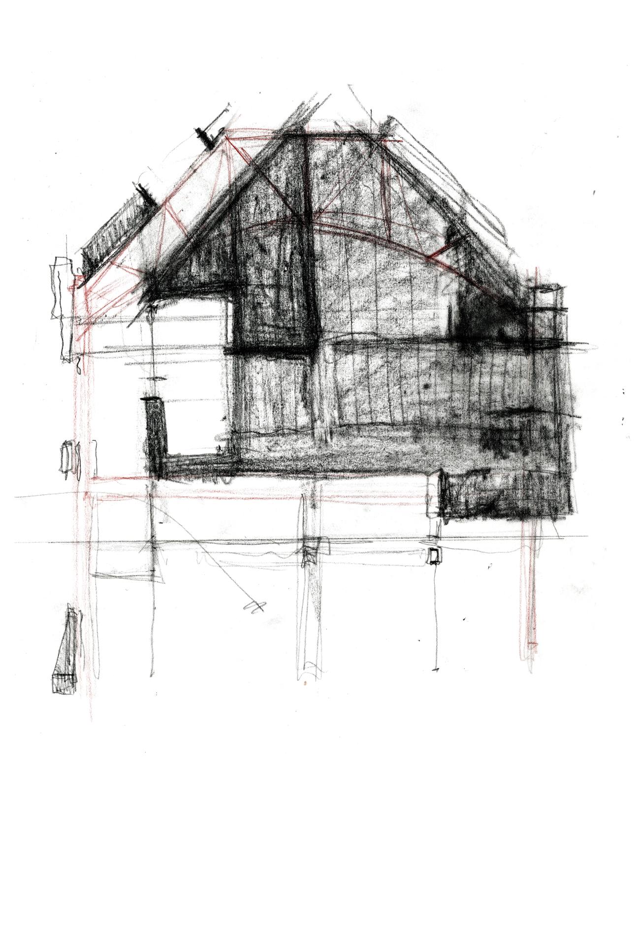
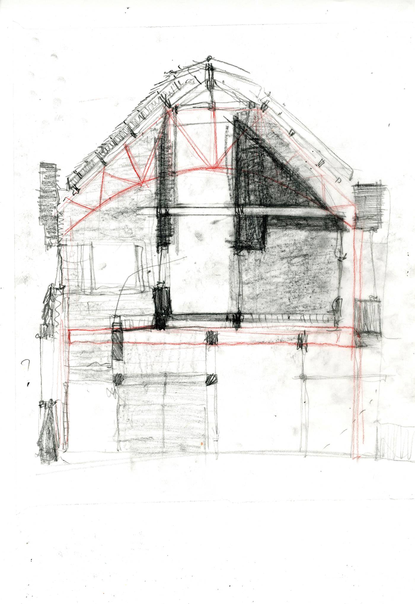
Initial Section Sketch

1:200 Ground Floor

1:200 1st Floor

1:200 Roof
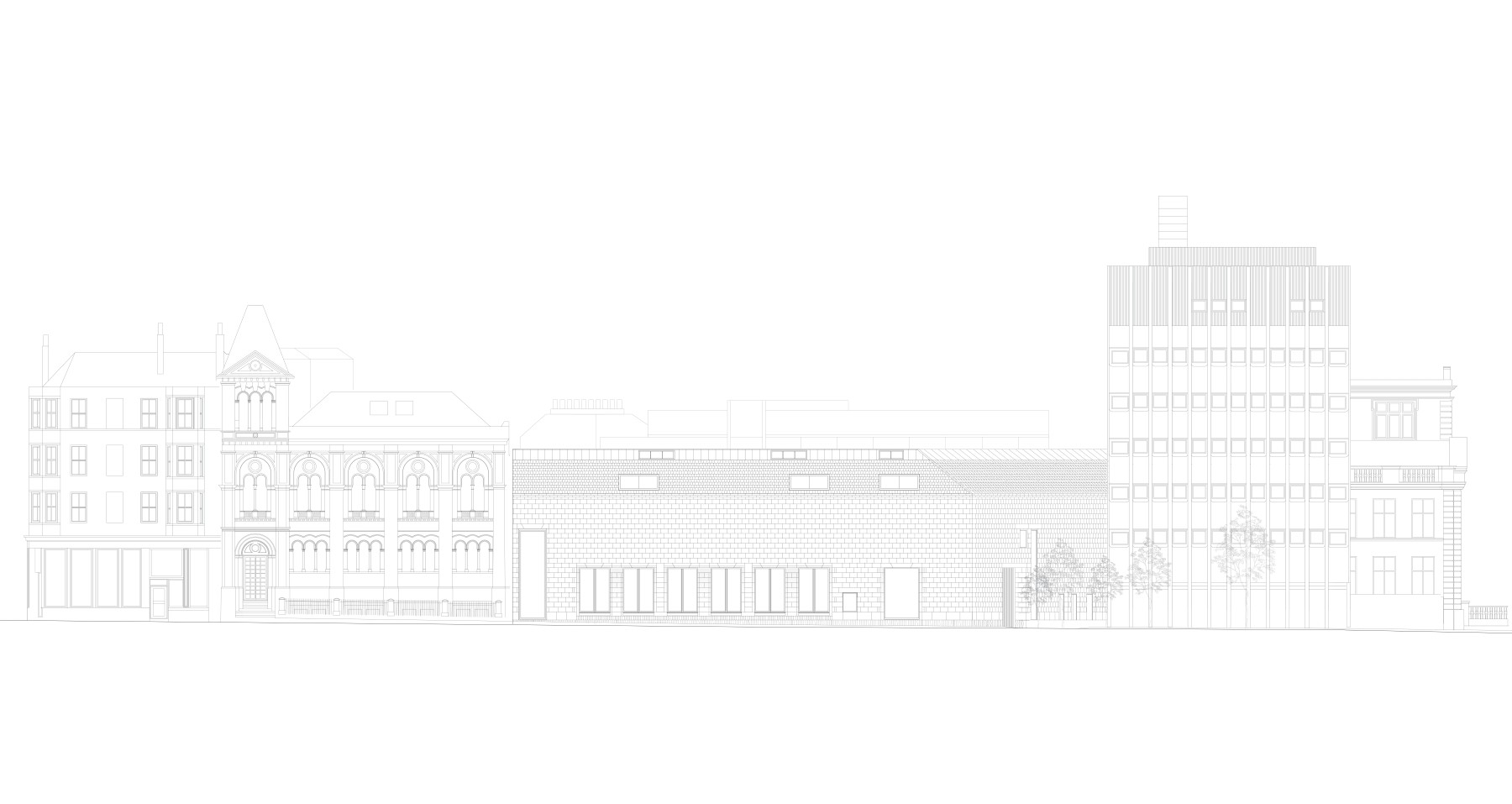
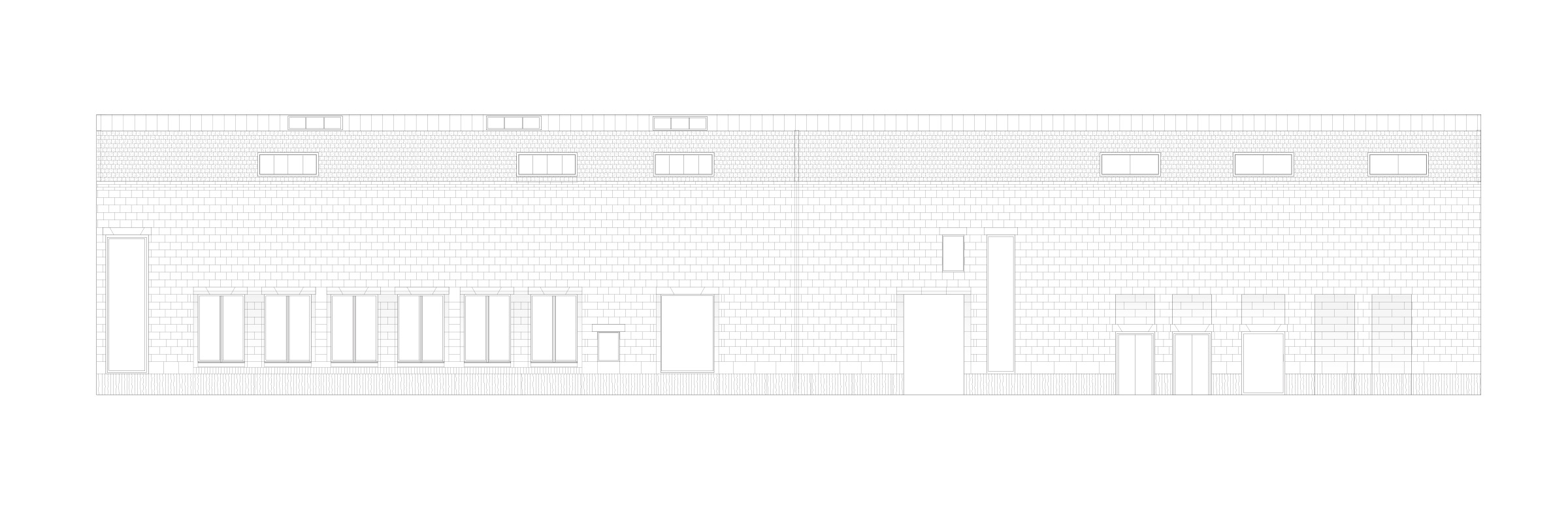
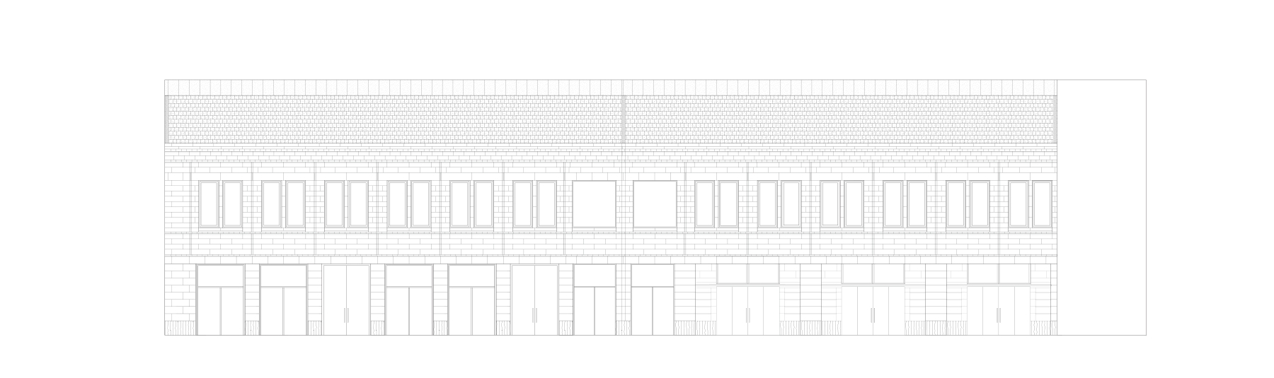
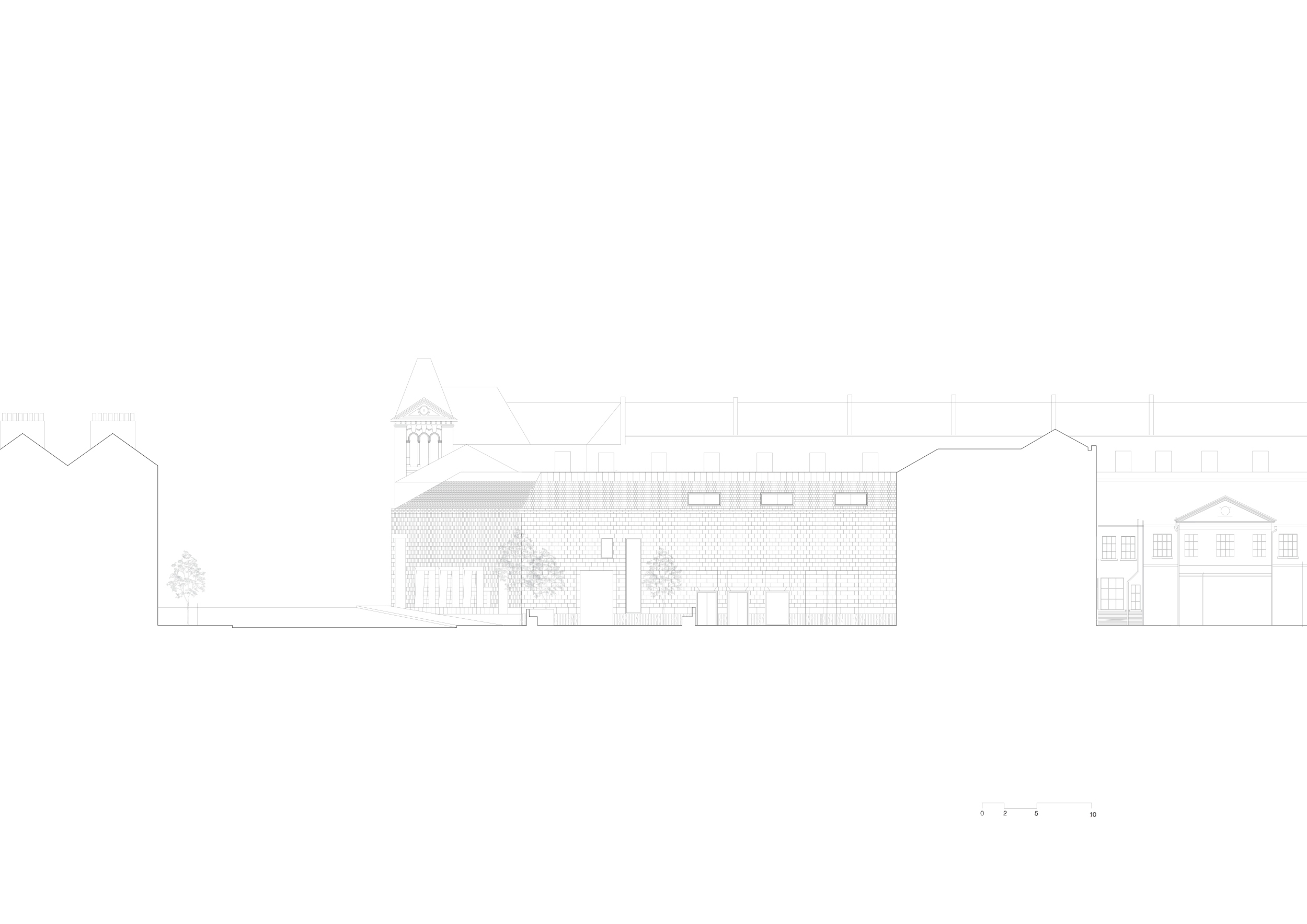
1:200 North Elevation
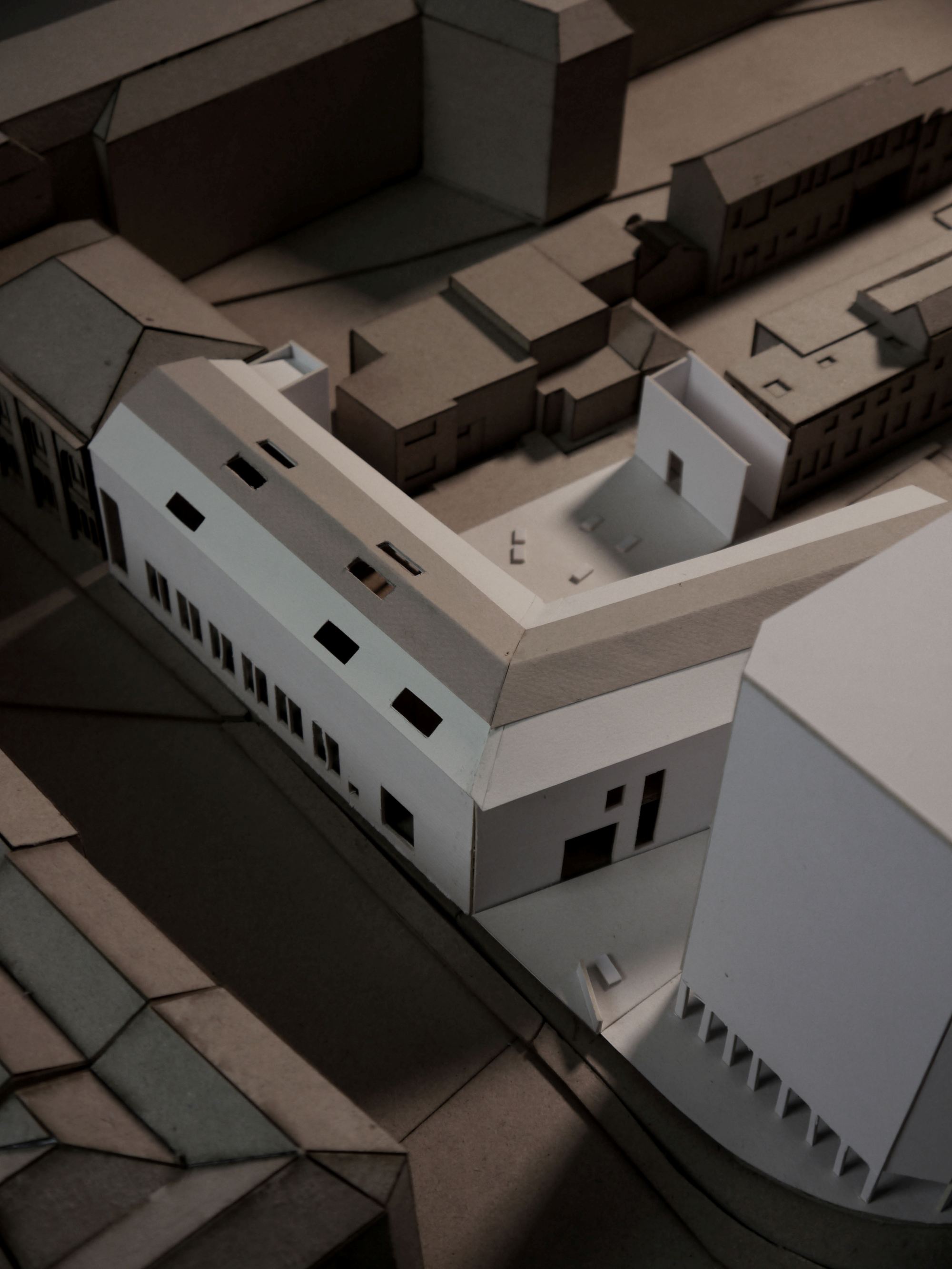
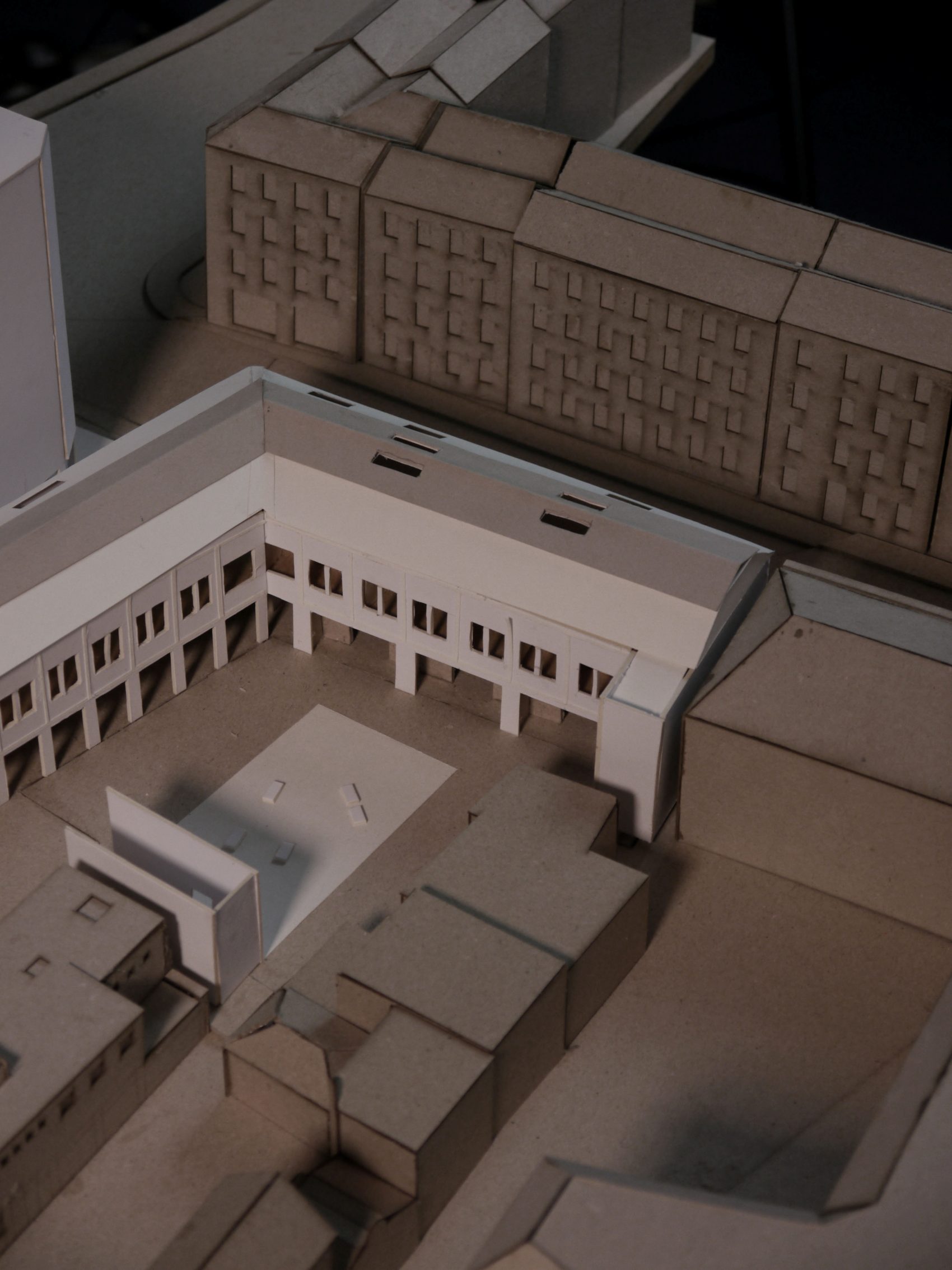
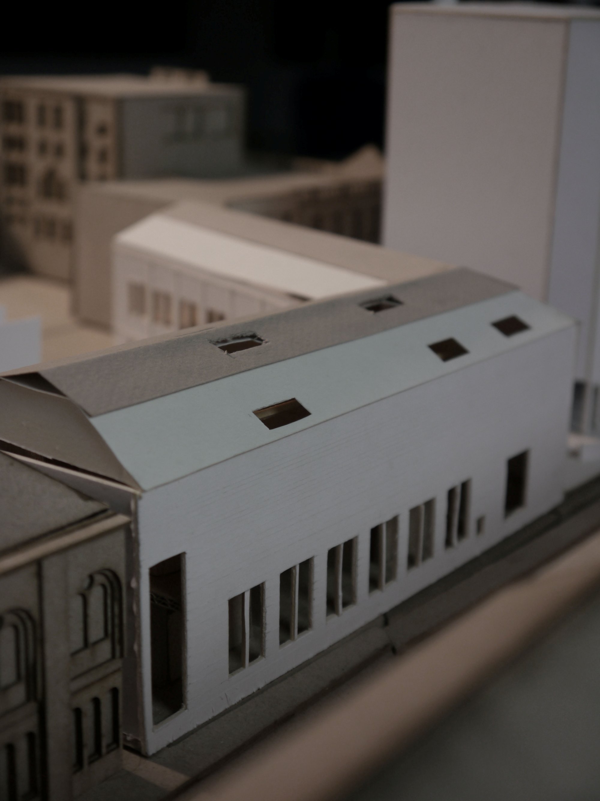
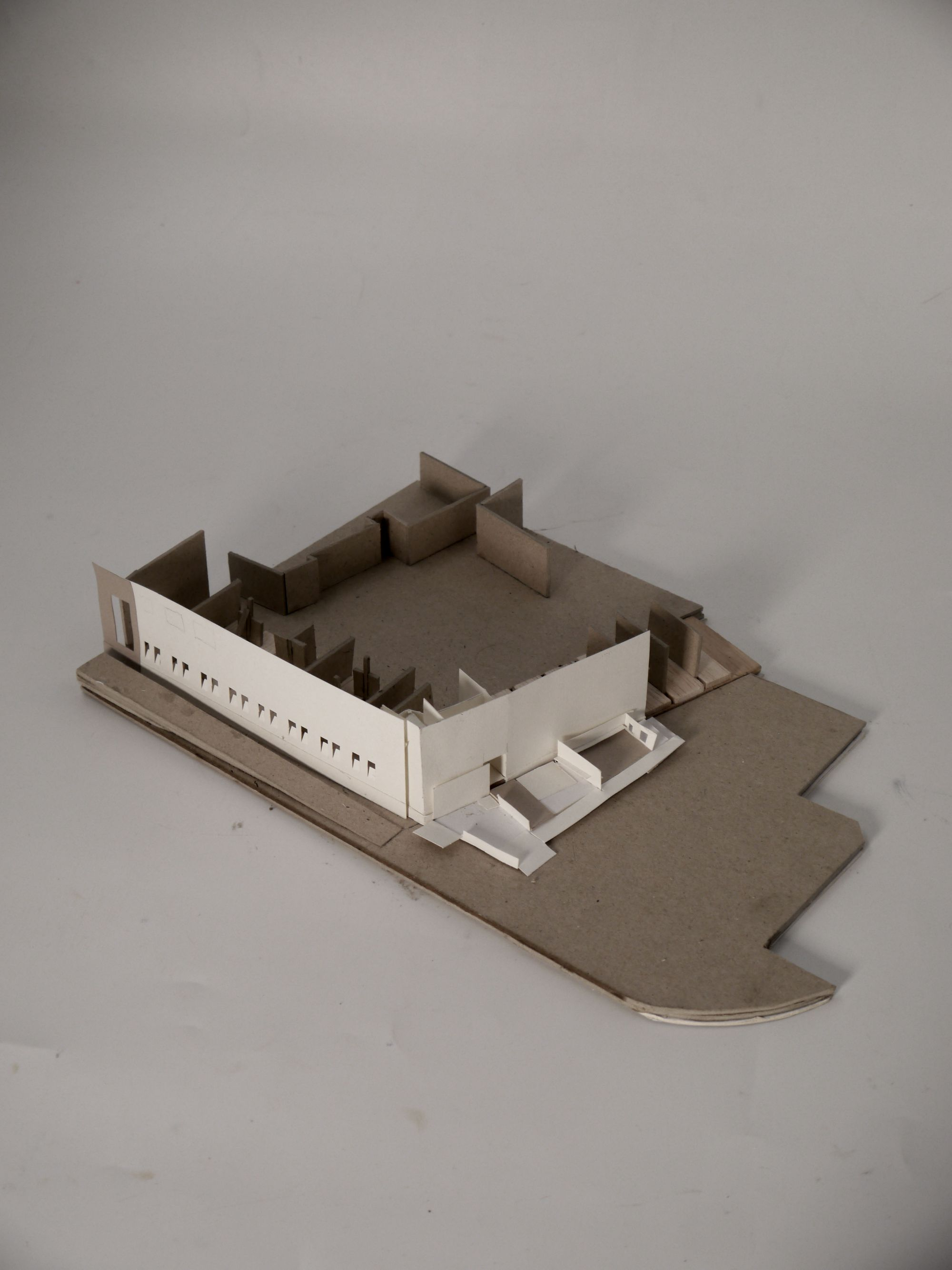
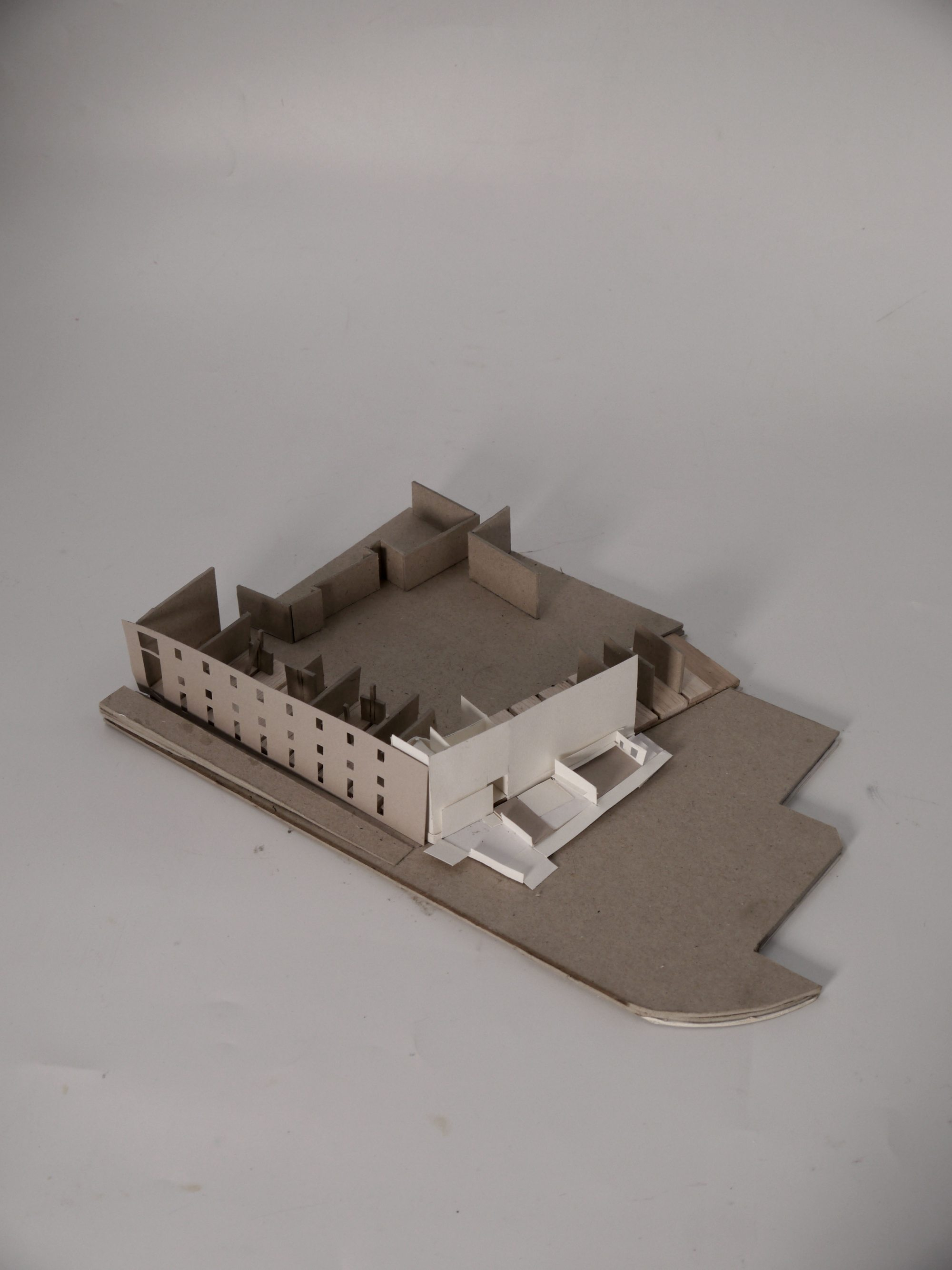
1:200 Model in Context
Design Parameters

Ground Floor - External Working Space

1st Floor Diagram - Timber volumes + Defining Lanterns
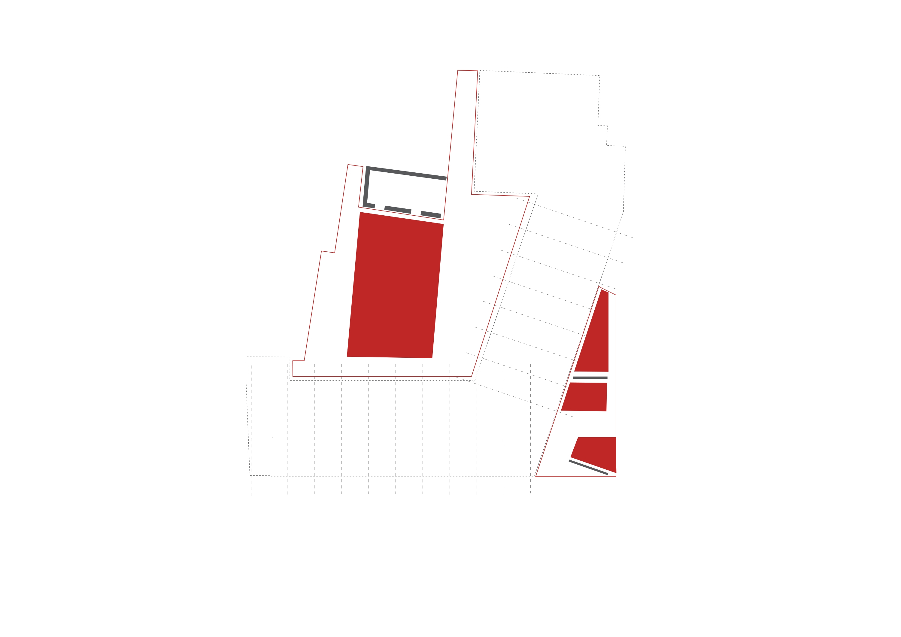
Building Mediates Courtyards
Reordering of Facades

New Circulation

Iterative Sketch

1:200 Workshop Section (West)
Entrance + Facade

Entrance + Courtyard
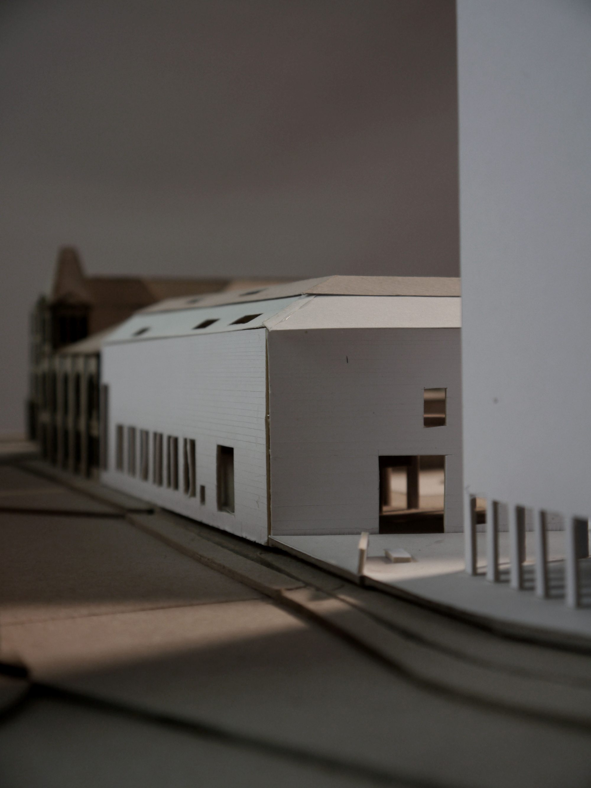
1:200 Model - Entrance
1:200 Model - "Civic" Facade
South-South West Elevation
North-North West Elevation
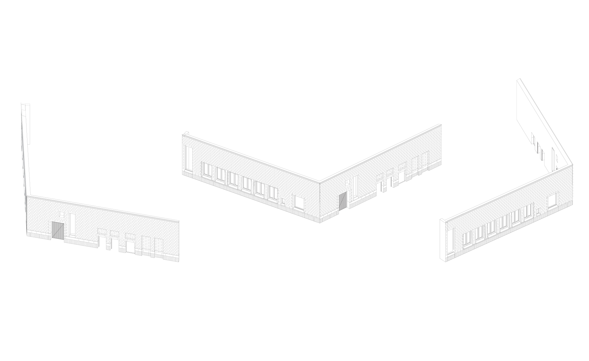
Existing North Elevation

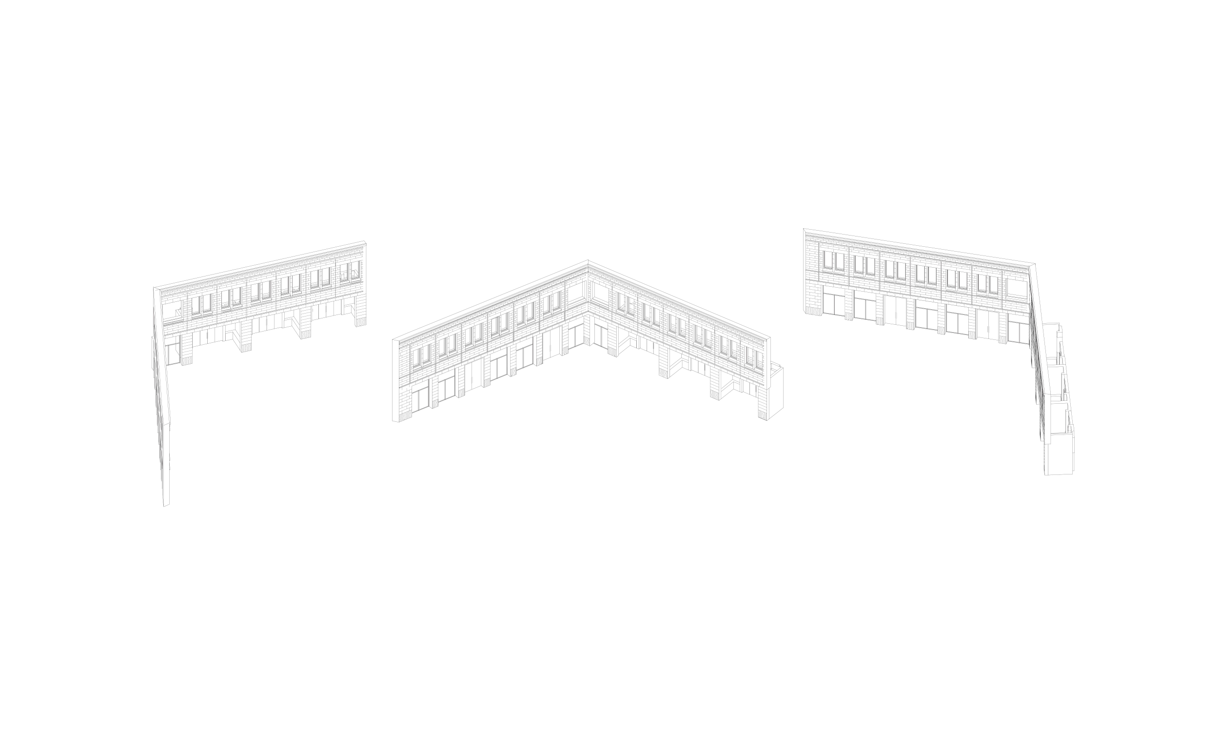
Proposed North Elevation
South-South West Elevation
1:200 South Section through Courtyard
Development - Civic Approach
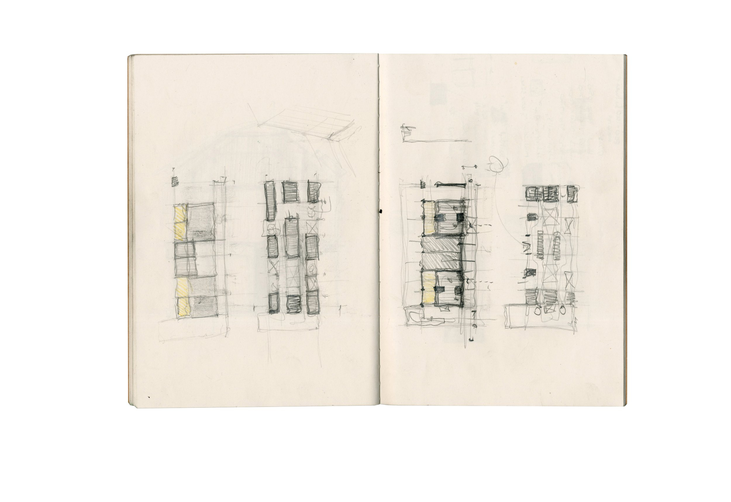
Entrance + Courtyard Tests
Facade Tests
Entrance Sketches

Entrance Tests

Entrance Tests
1:200 Entrance Elevation
Tectonic Attitude - Workshop & Material Library
A stone facade acts as the buildings shell, in which a stereotomic ground floor, composed of existing & relayed brick masonry walls define “heavy” workshops. This is juxtaposed with a filigree, timber focused first floor, reflecting the studio and library based activities. Hence, the material language is a reflection of the programmatic requirements of each specific space. The existing frame provides a structural system for the two tectonic approach to sit be placed within and around. The decision was made to retain (without alteration) the structural steel frame and 70% of the internal racking walls, whilst the facade material deemed to be altered into an entirely new composition. The decision to do so was to emphasise a new civic frontage, thermal upgrade and to ensure a deal of longevity and durability from the performance of the facade. This was achieved by utilising the growing capabilities of Scottish stone suppliers and by carefully reusing & reorientating the existing stone ashlar, which was retained. This intervention was intended to be more permeant, to emphasise that this build has the potential to have a civic longevity. The internal material decisions were driven from the perspective of adaptability, so that internal programmes can be altered whilst the shell of the building remains, hence the design focusing on re-assembly
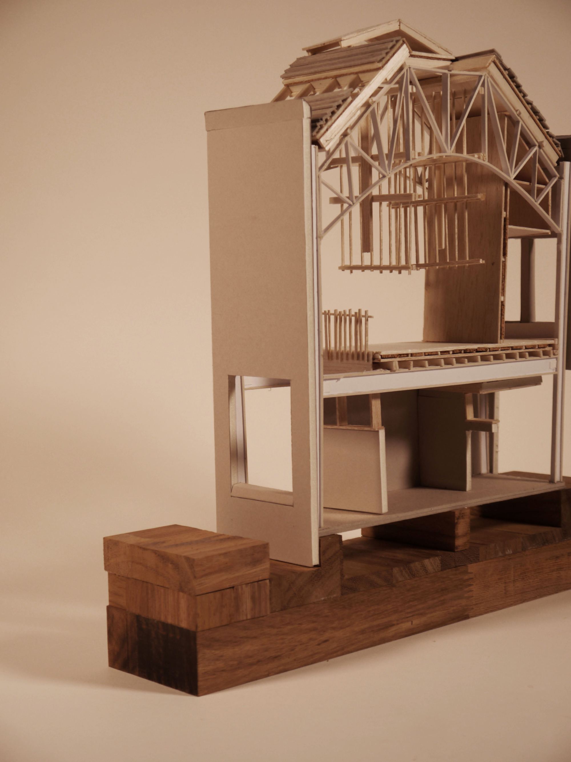
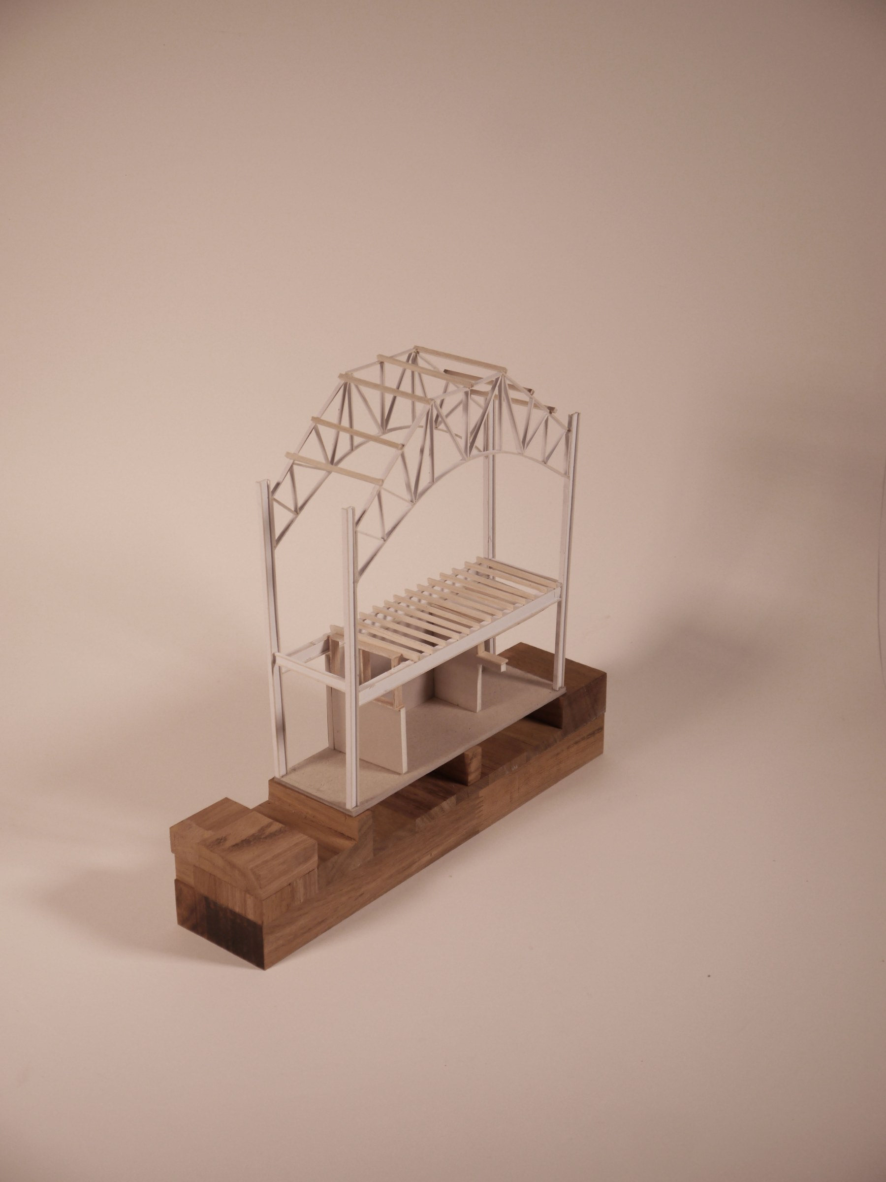
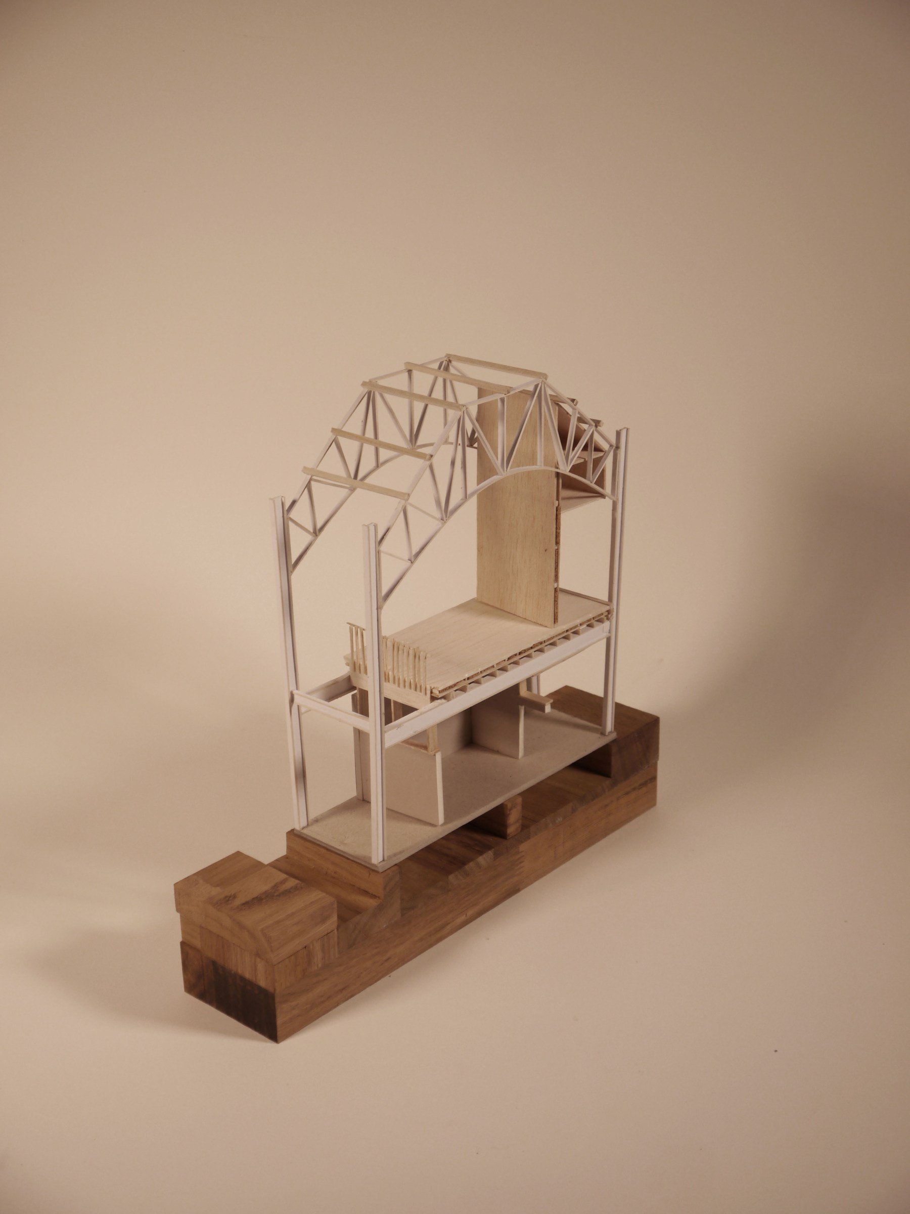
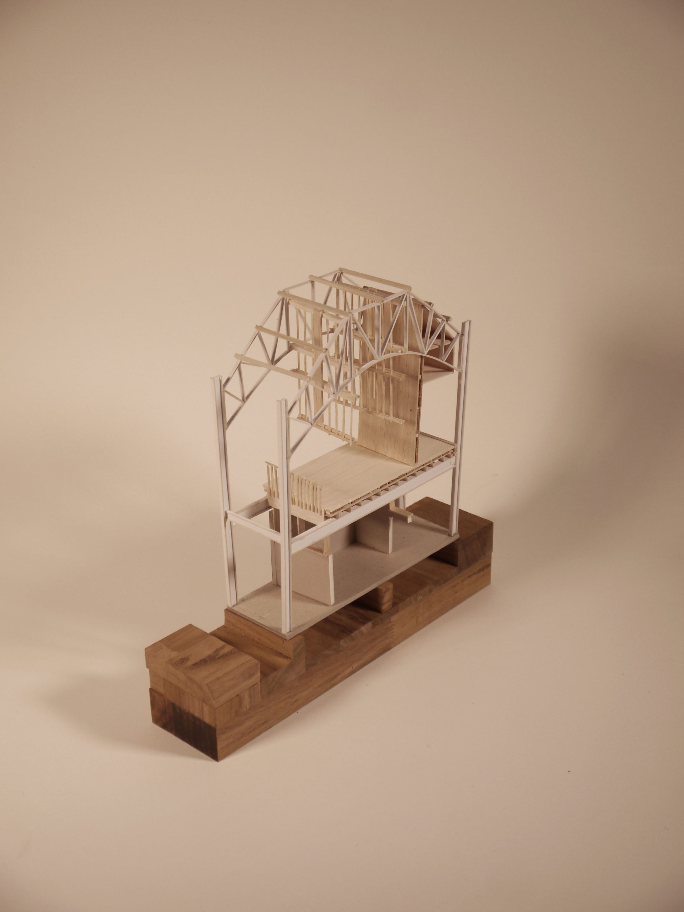
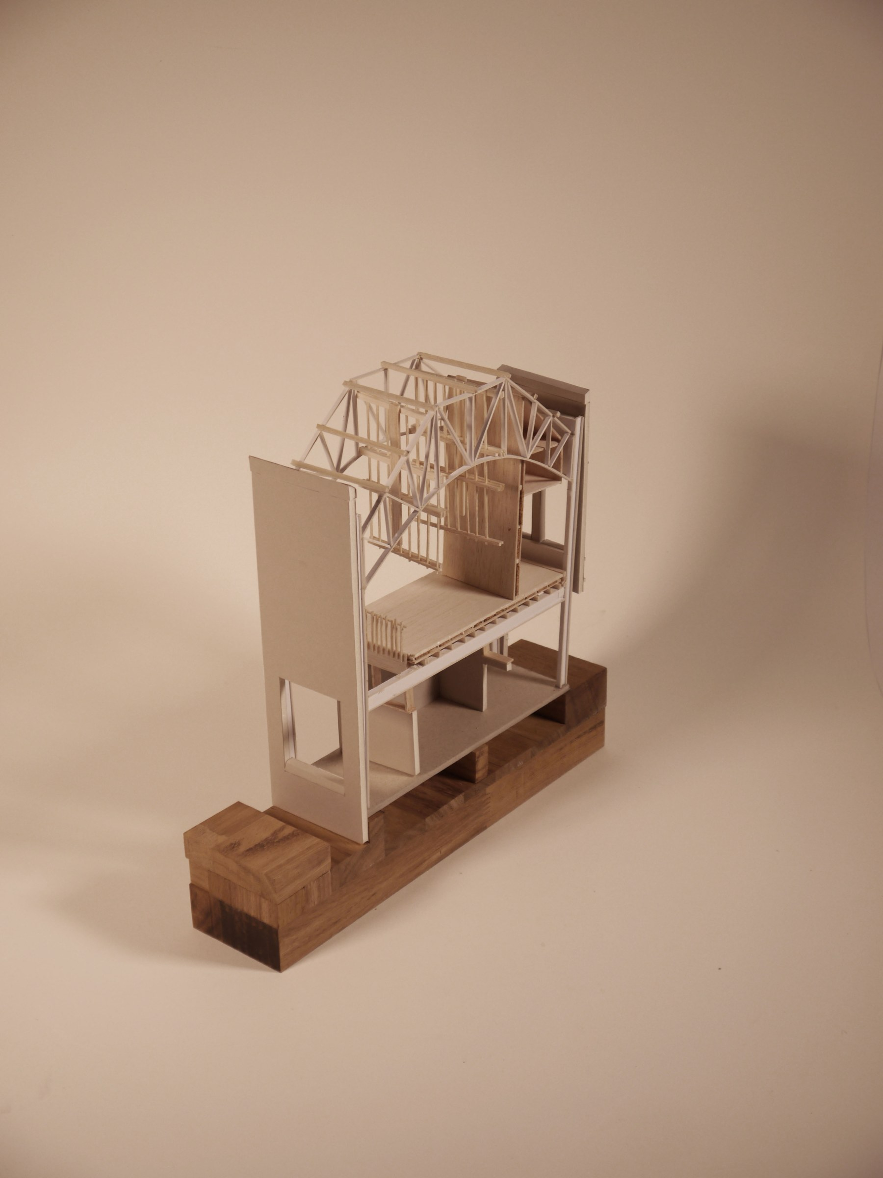
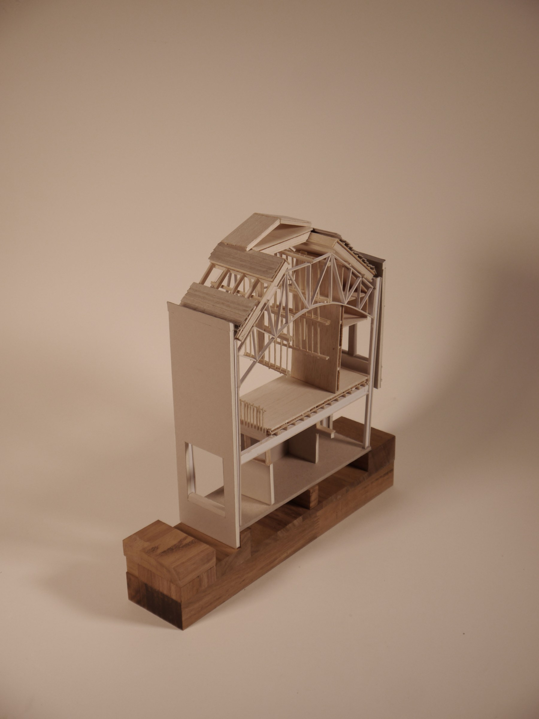
1:50 Sectional Model -North Elevation
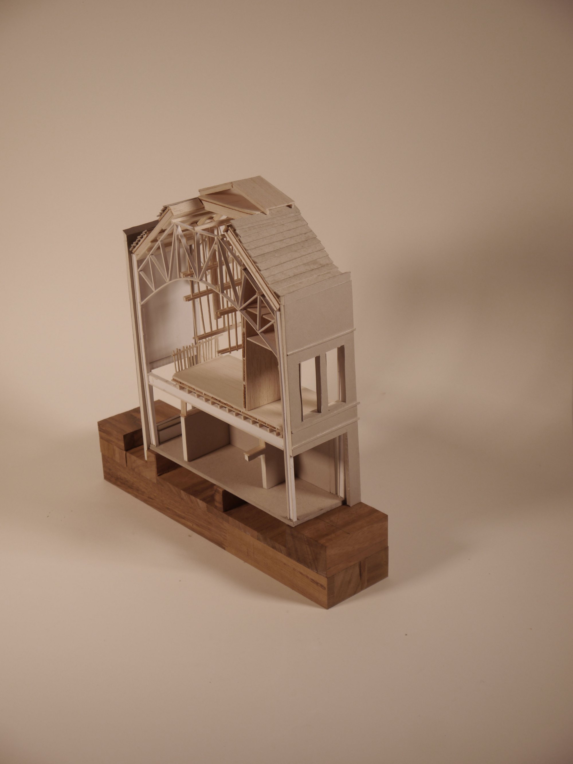
1:50 Sectional Model -South Elevation
1:200 Workshop Section (East 1)
1:200 Workshop Section (East 2)

1:200 Workshop Section (East 3)
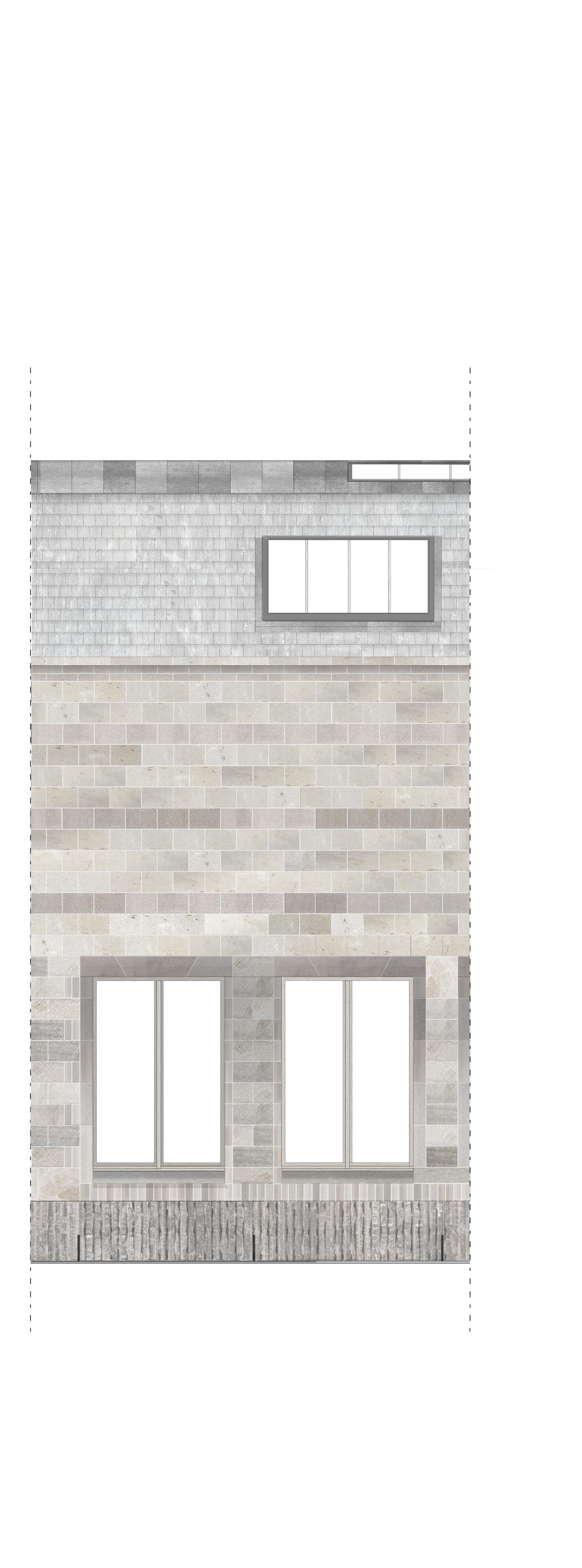
North Elevation Bay
South Elevation Bay

Workshop Organisation

Workshop Organisation
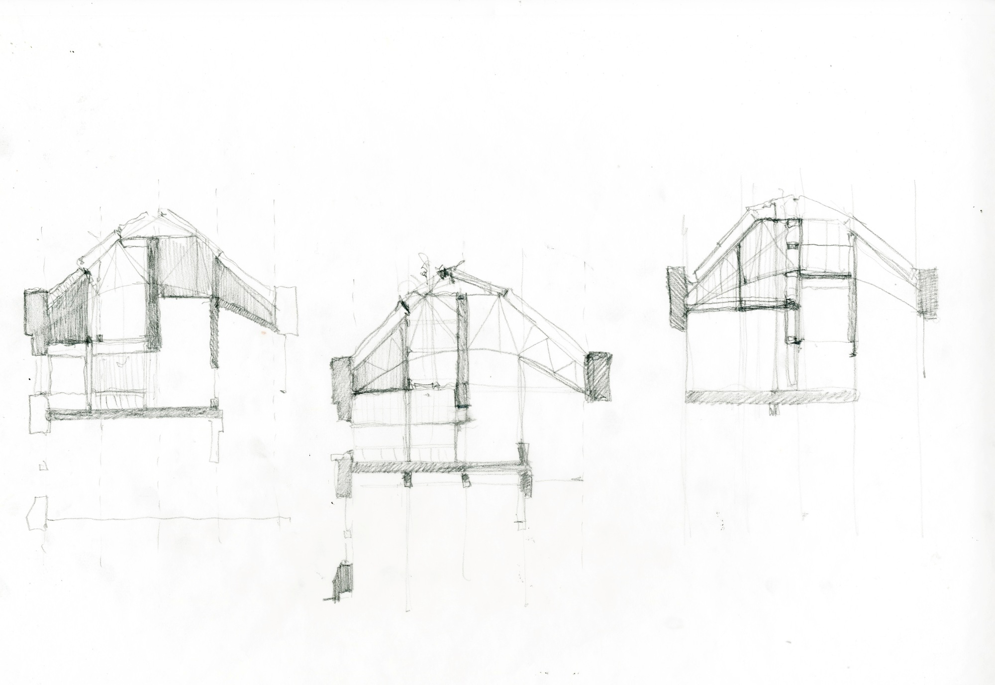
Section Tests
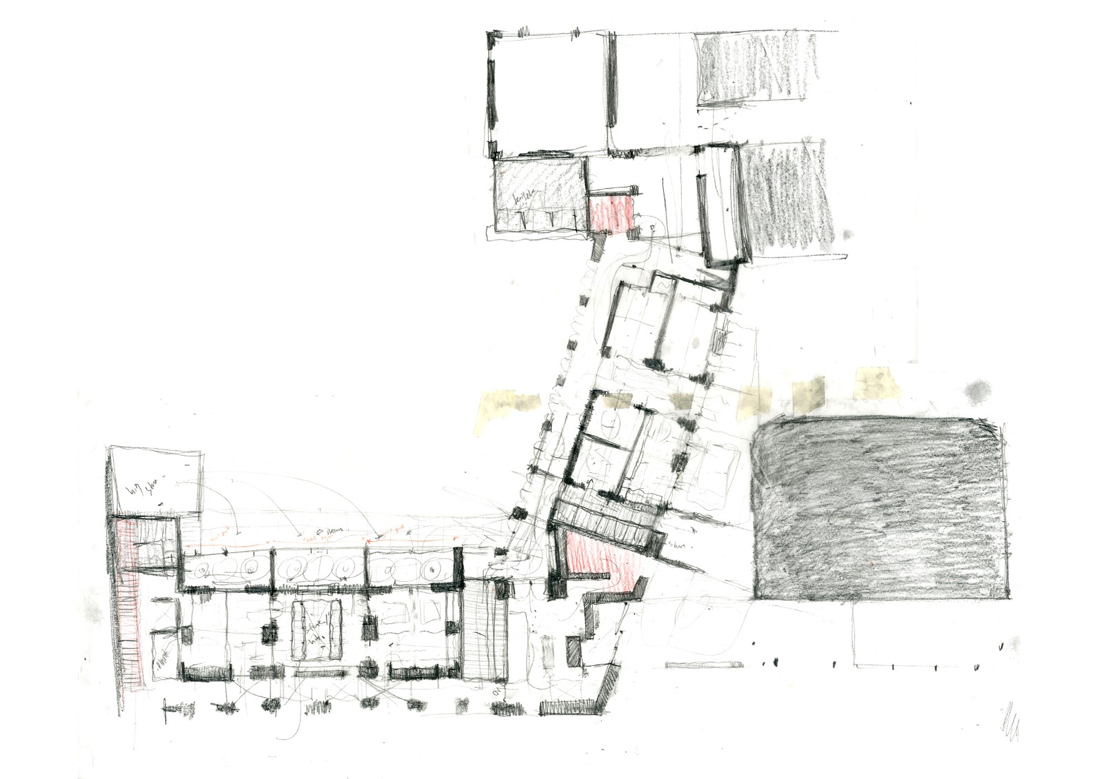
Plan Diagrams

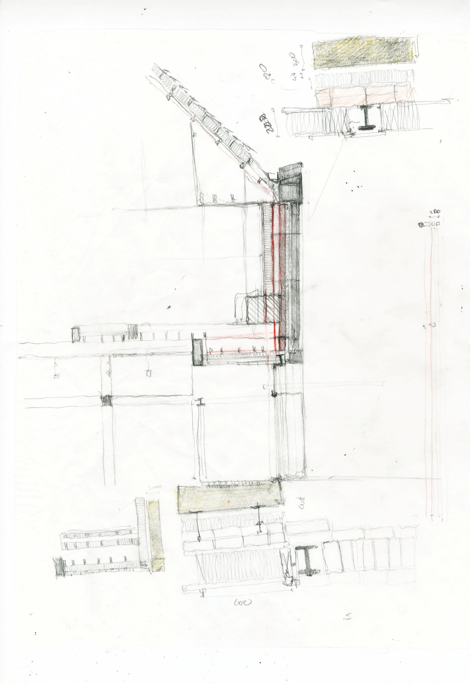
Initial 1:50 Technical Exploration
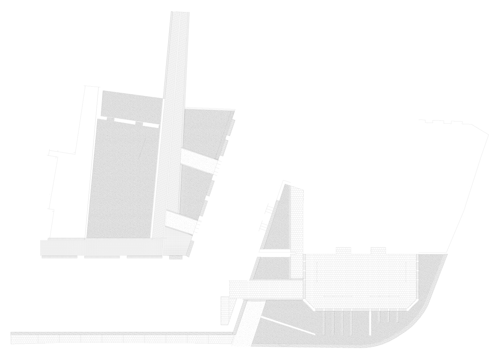
1:200 Long Section through Workshop
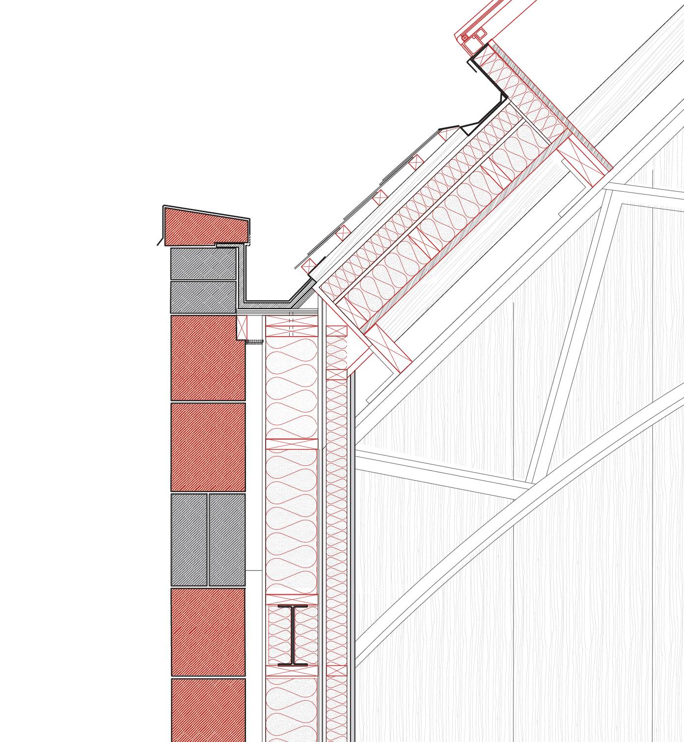
1:50 Technical Detail
Existing Frame
Masonry Ground Floor (mix of reused + new brick masonry)
Scottish sourced timber Cassettes
Defining Lanterns
Facades (Cavity + Insulation)
Insulated Roof
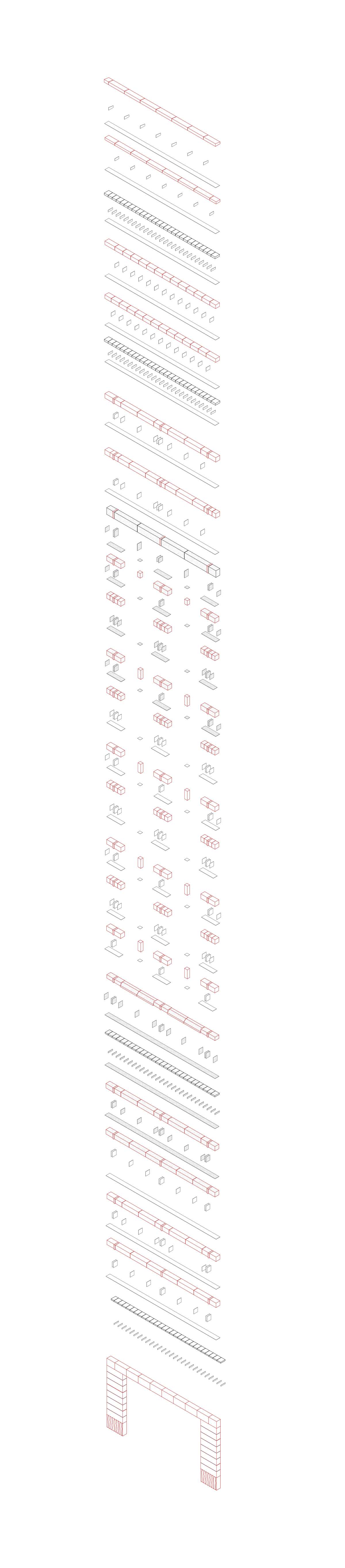
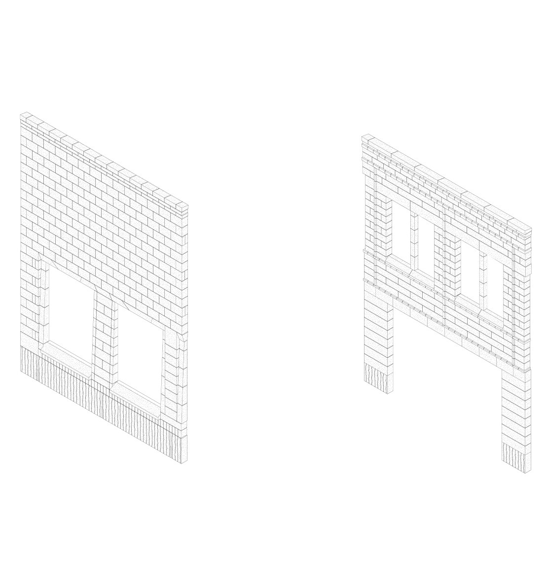
Shell - Stone, Reuse + Addition
The manufacturing and resource souring is considered applied and used to articulate changes in fenestration, and stone detailing. Existing Ashlar is reused, being cut, repositioned and composited to form load bearing blocks. New stone is used to provide a further layer of durability and permanence, whilst the timber additions are intended to be removed. The stone is specified to be thick enough (300mm) such that it has more adaptability in being reused in the future. Using undressed stone such as blocks which express saw chatter and drill marks, are prioritised to allow for the quarry to efficiently extract the quarried stone and for each block to be more efficiently manufacture. Ensuring each block is 300mm square and less than 900mm equal in length, allows each 300mm slab cut from the primary saw to be efficiently divided into equal widths and lengths. Reducing waste by not reject blocks with small defects us further productive for the use of stone within the facade. This size also suits the geological makeup and bedding of Darney Quarry as this is the most materially efficient size that can be made out of the raw blocks. The reusability of the stone us further enhanced by allowing the block to be thicker, meaning it can be cut down for different jobs, if mistakes in the manufacturing process deem the whole block to be insufficient. Therefore, this not only makes the process sustainable in mitigating waste, but reduces the overall cost through a modular system which does not require an extensive finishing process.

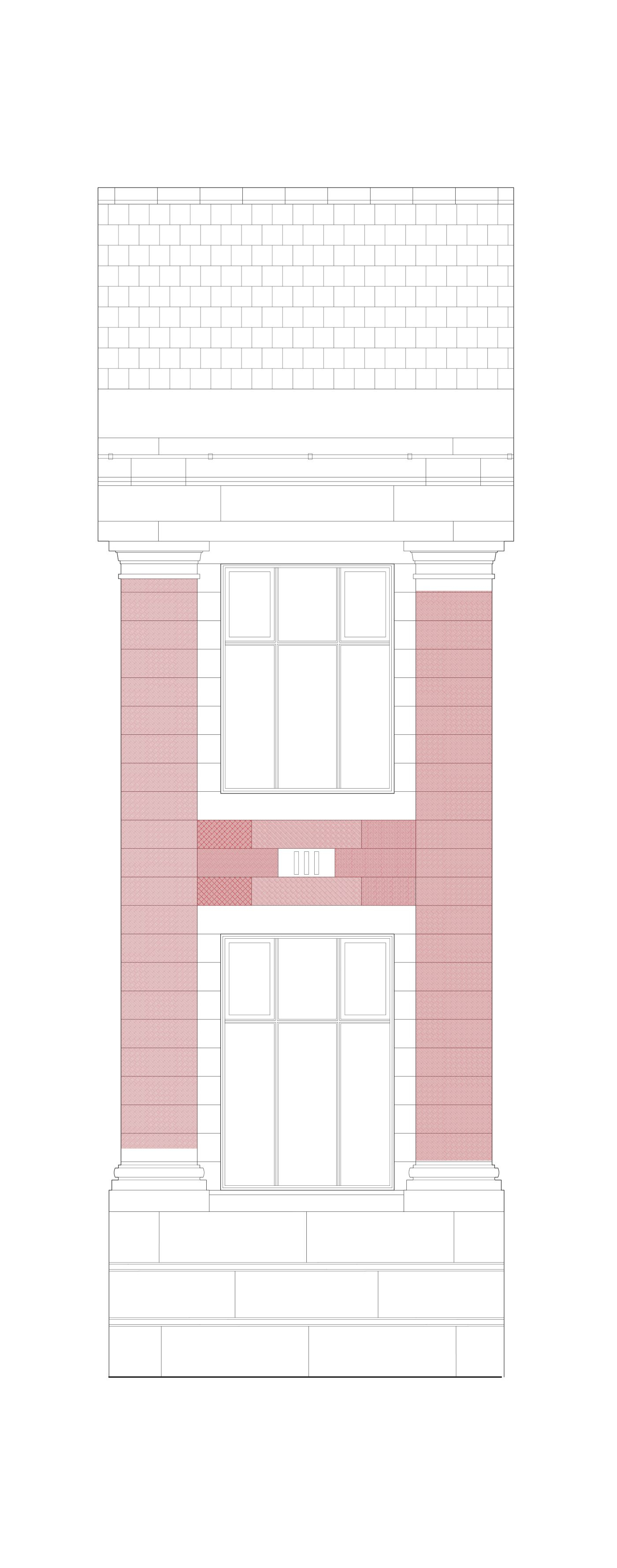
North Facade - Window Opening Stone Layout De-constructed
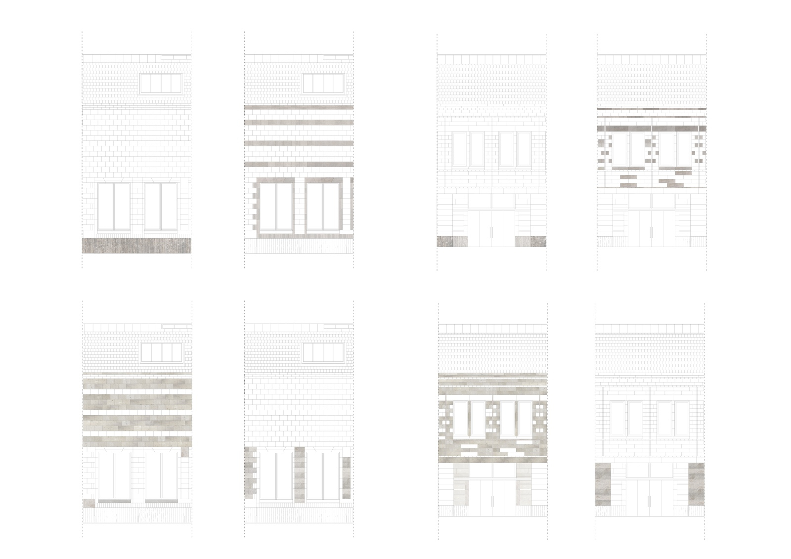
Stone Finishes - "Drilled Face" "Reused Ashlar" "Unfinished from Saw" "Saw Chatter"
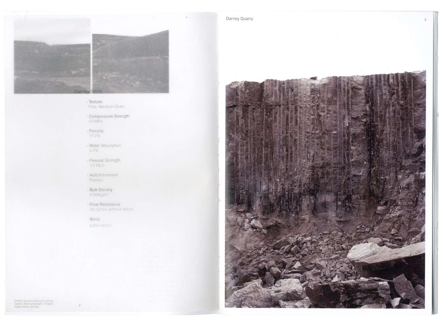
Darney Quarry - Striations from drilling + extraction process

2m Diameter Primary Saw Blade

Darney Sandstone "Biscuits" - Awaiting Secondary Sawing

Touching Masonry
South Facade Stone Layout De-constructed
North + South Facades

North + South Facades - New Stone

North + South Facades - Reused Stone

Post Tension Stone Bulkhead Detail - 1:10
Parapet Detail -1:10

Foundation Detail - 1:10
Reuse - Frame + Brick Masonry

Removal of UC's to form larger south facing openings
Existing Brick Masonry reused in Courtyard paving

Existing stone positioned in new facade

Stone Reused for Lintels
Existing Ashlar blocks re-orientated + re-positioned
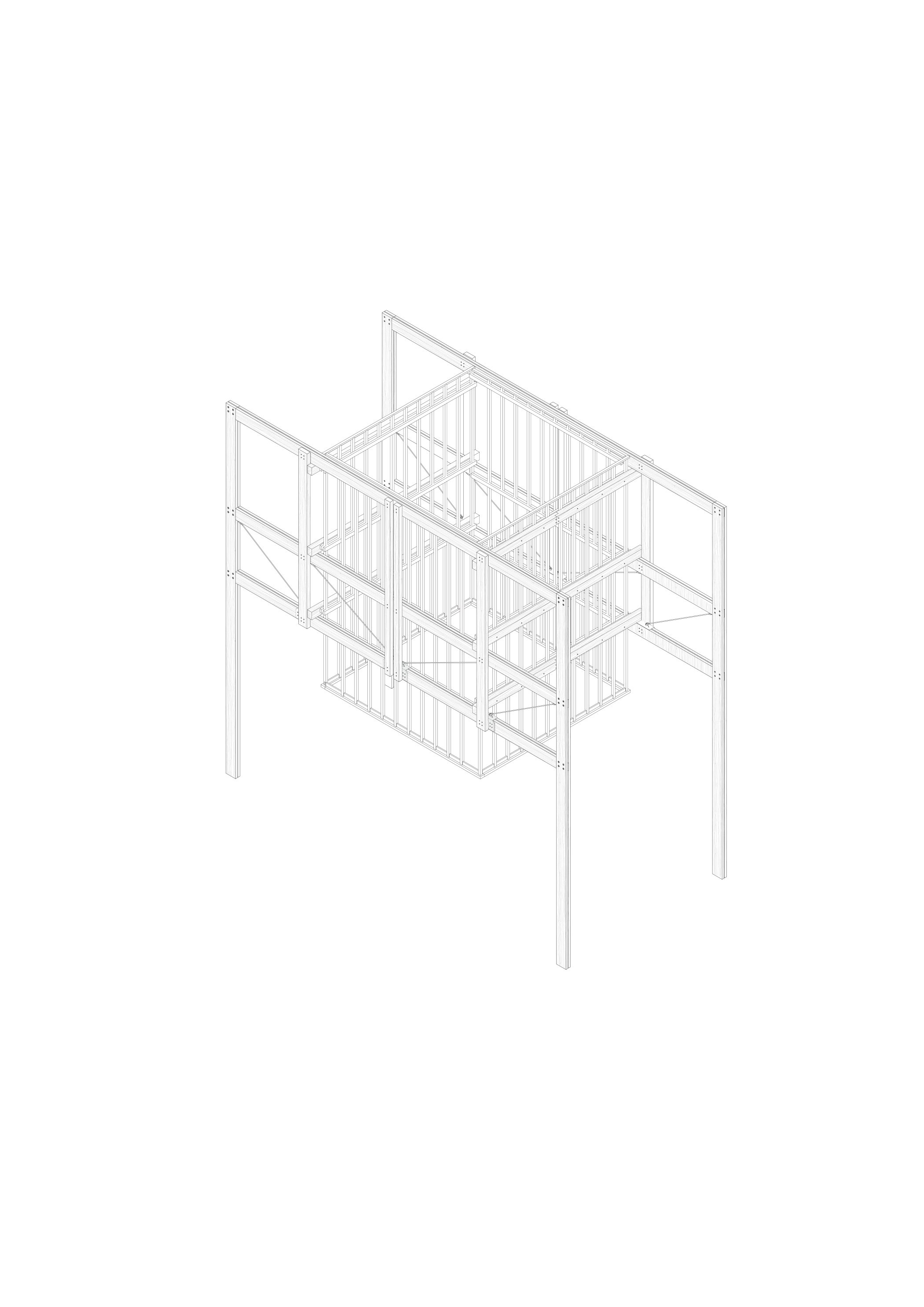
Lining - Timber, Re-assembly
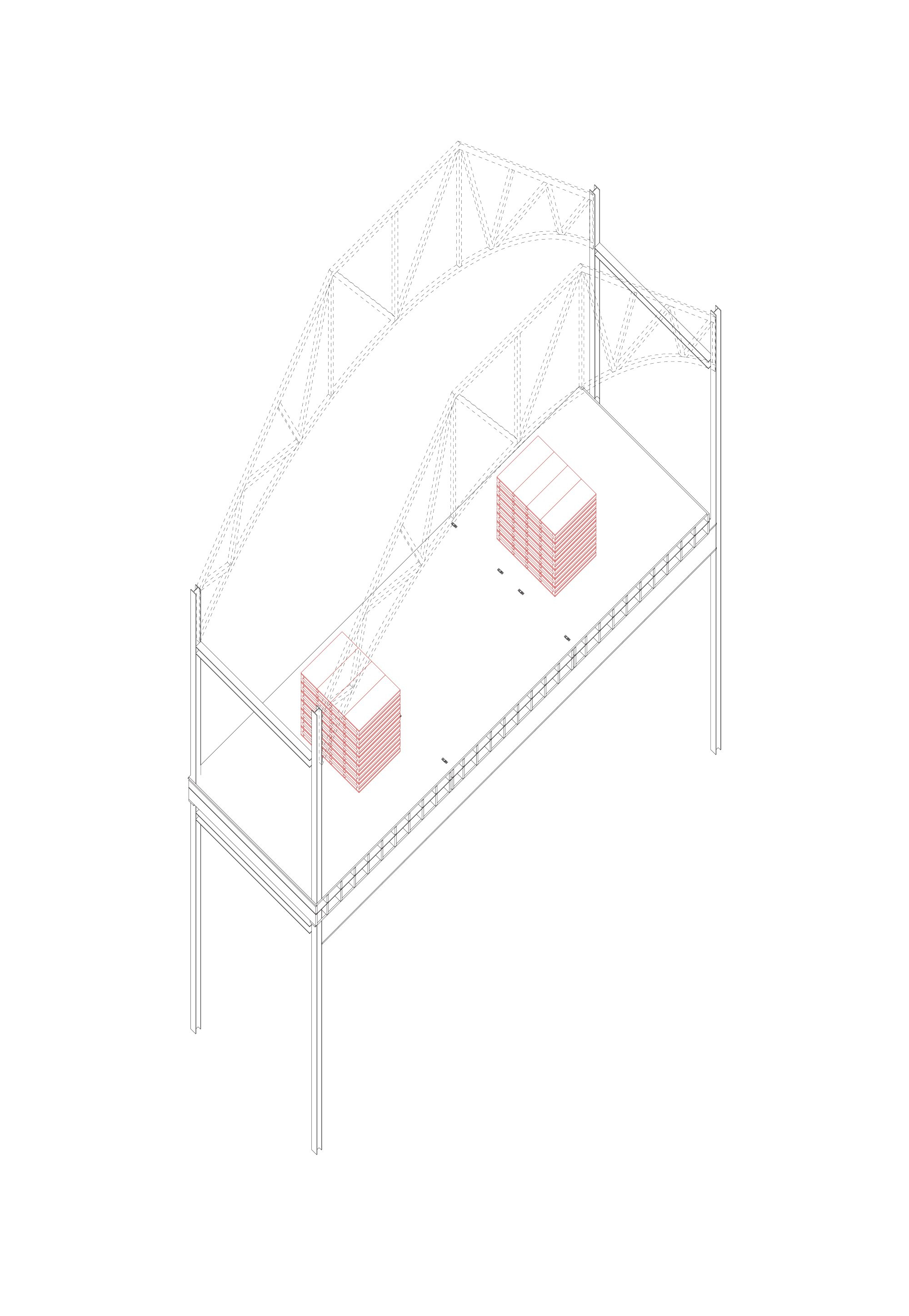
Timber linings fill the first floor, made up of disassemble cassette configurations, delivered prefabricated and assembled on site. The timber lanterns suspended from the existing trusses and braced by a new timber structure, all using C16 specified by James Jones. The sizes are all standard, hence the manufacturing process does not need to become bespoke for the timber itself. Structurally, the use of flitch plates and ties allow the timber to be used for more challenging tensile purposes and for each element to be taken apart, helping assembly and re-assembly. The use of Cassette walls, also designed for re-assembly, allow for the internal programme of the building to be efficiently altered. Their composition allows for the walls to be constructed and transported by hand, useful as this intervention requires access via stairs. The structural composition of each wall is intended to mitigate the use of fixed connection between each element, and for the timber to be of standard lengths and thicknesses.
1st Floor - Timber volumes designed for re-assembly
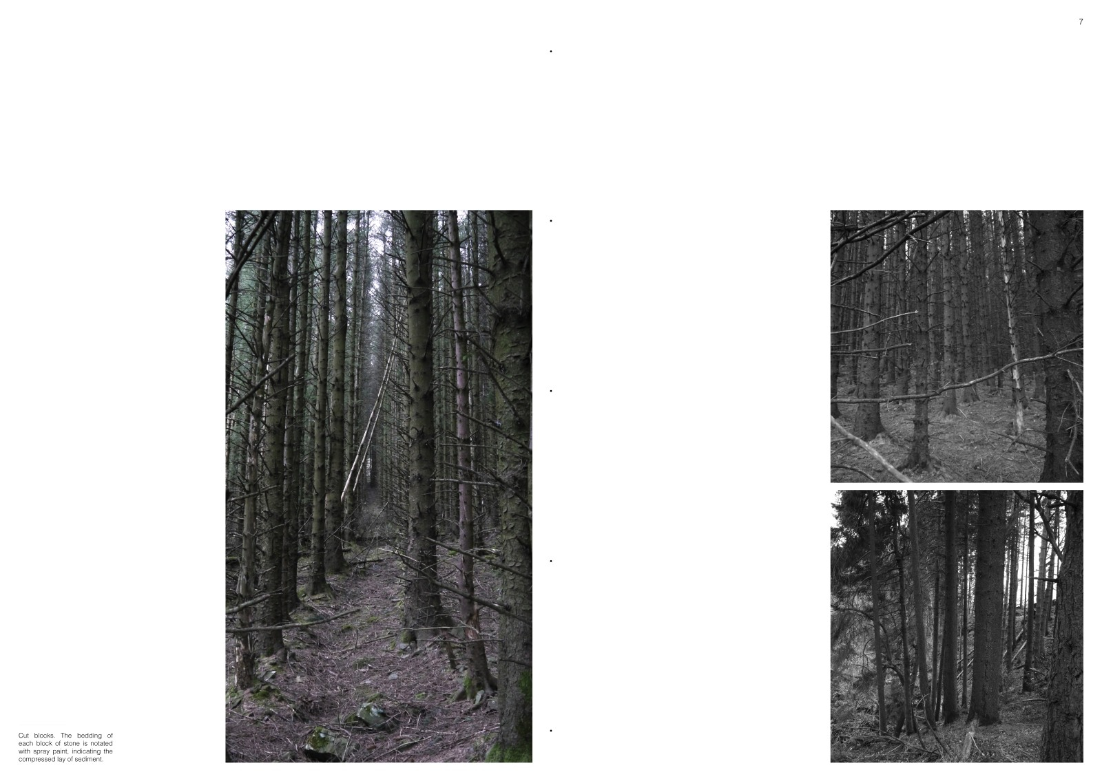
Forest- Sourcing
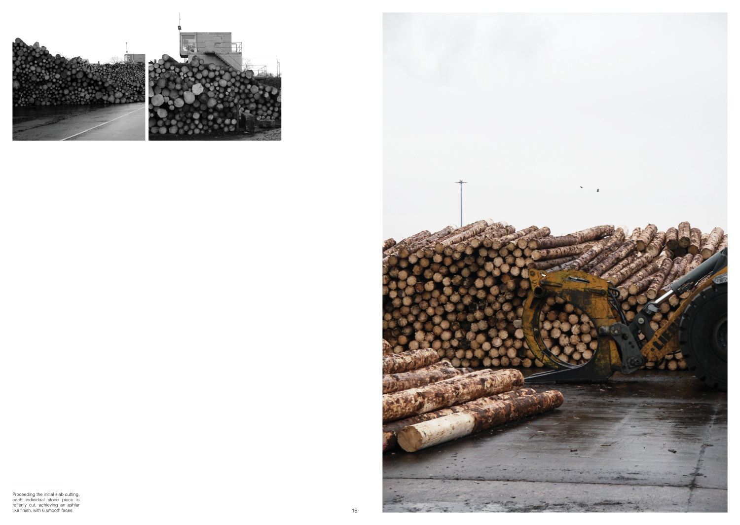
Log Storage + Primary Saw Preparation
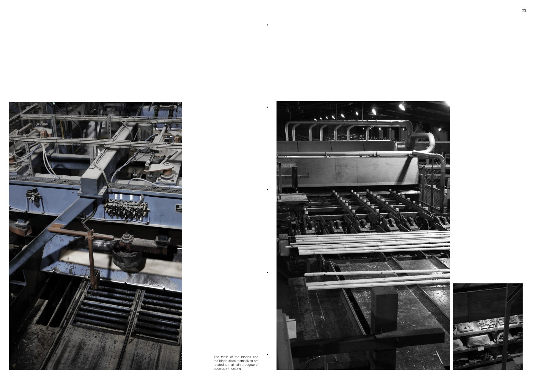
Primary Sawing
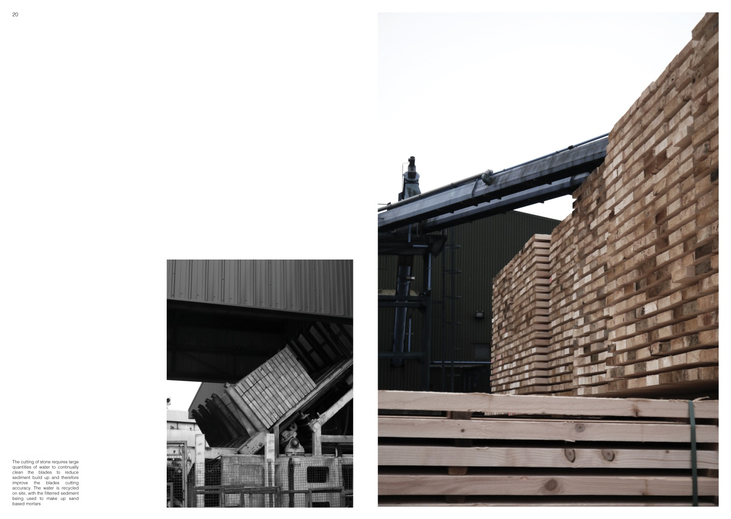
Kiln Drying + Packaging Preparation
Suspended Lantern - defining gathering spaces
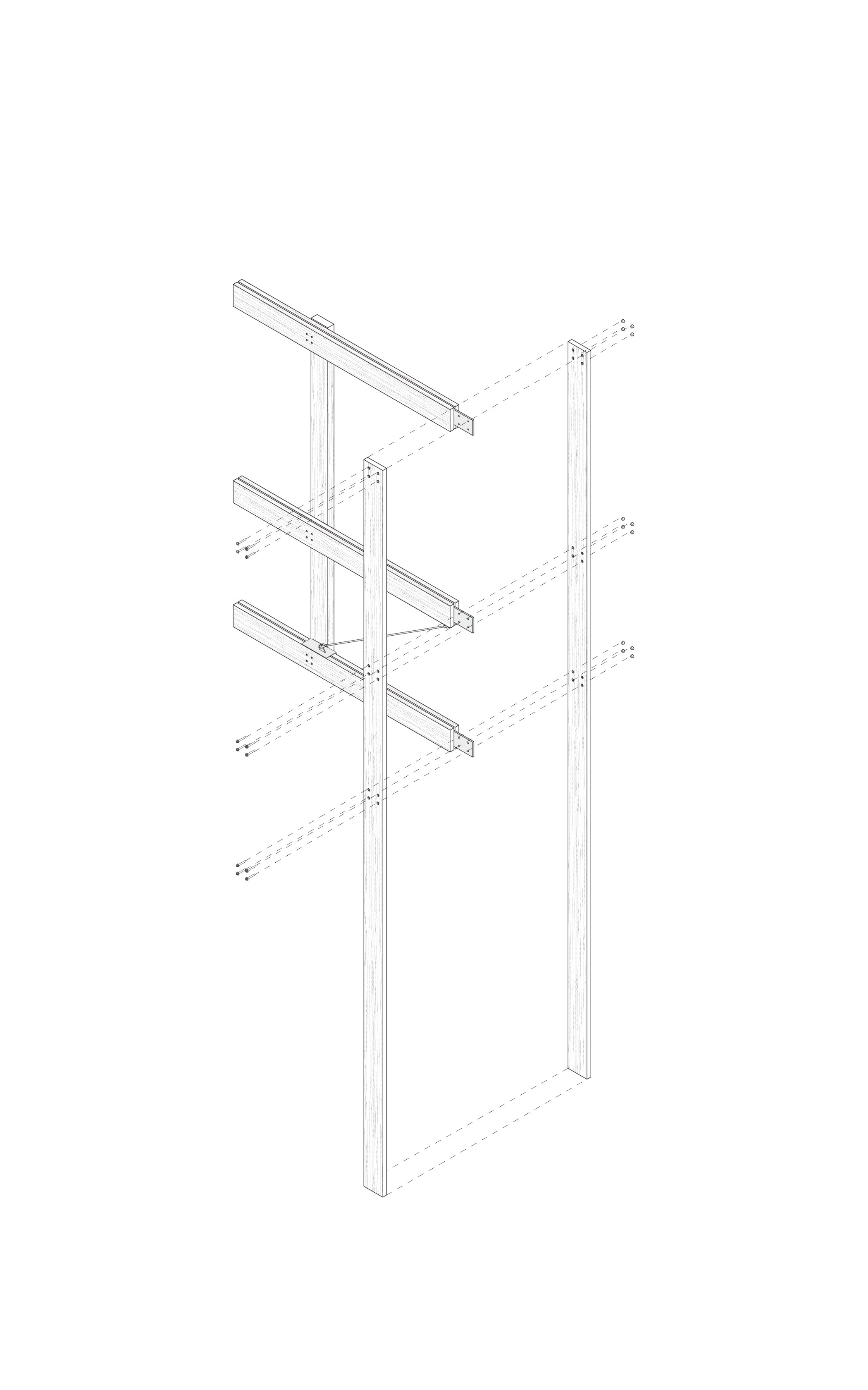
Suspended Lantern - Flitch plated Beam to column connection (concealed by internal walls)
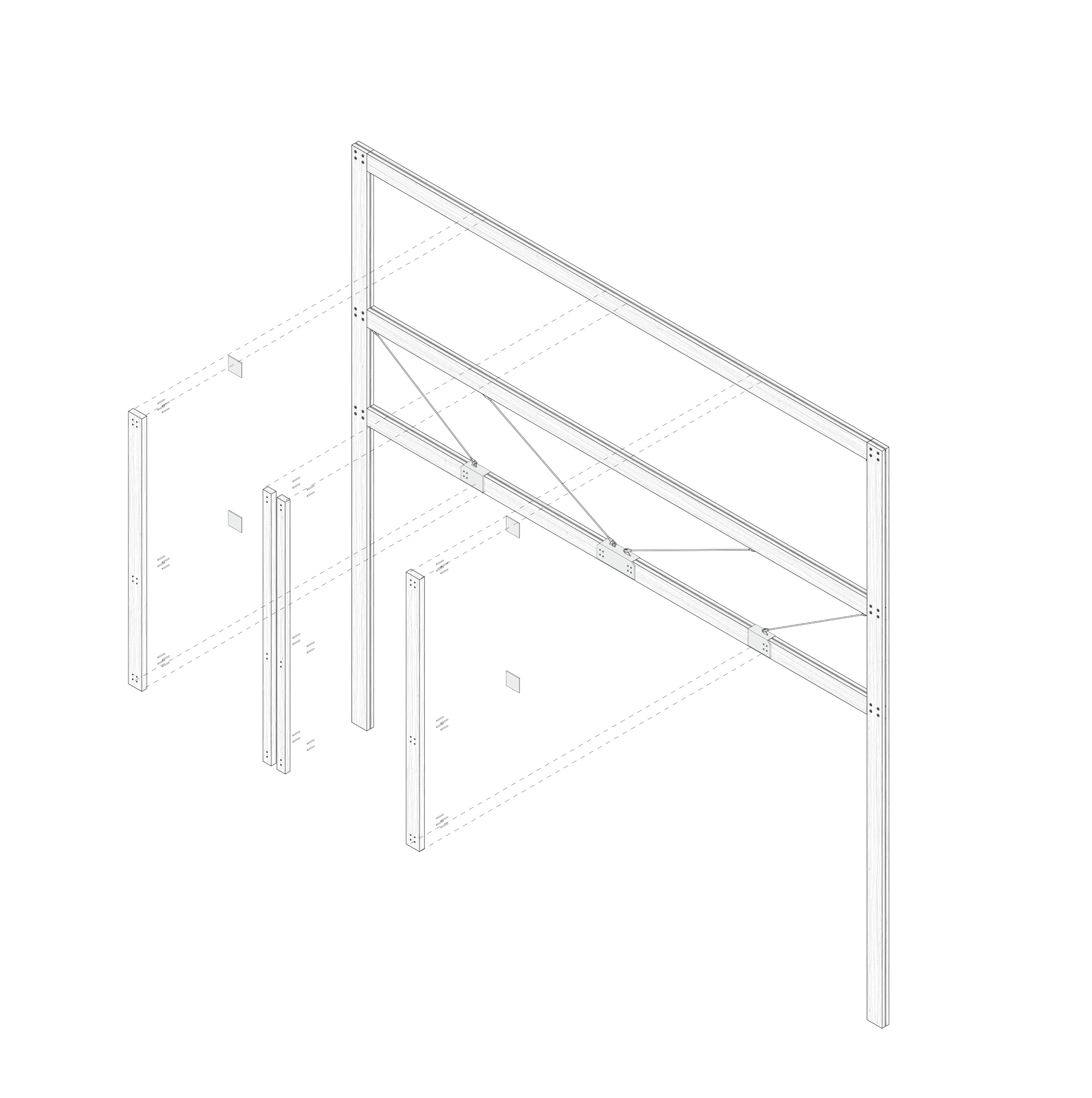
Suspended Lantern - Ties bolted between beams (improve tensile strength whilst using standard timber sizes)
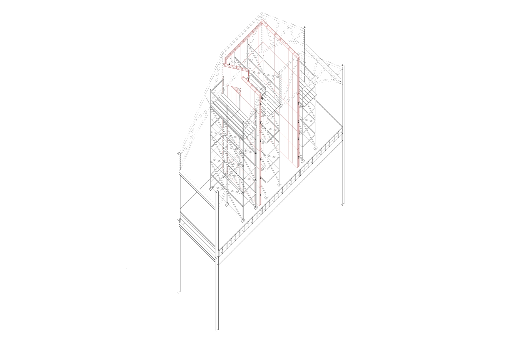
Cassette Wall De-construction - Internal Scaffolding Constructed

Cassette Wall De-construction - Panels Removed using Pully

Cassette Wall De-construction - Panels Removed by Hand
Cassette Wall De-construction - Stacked Panels
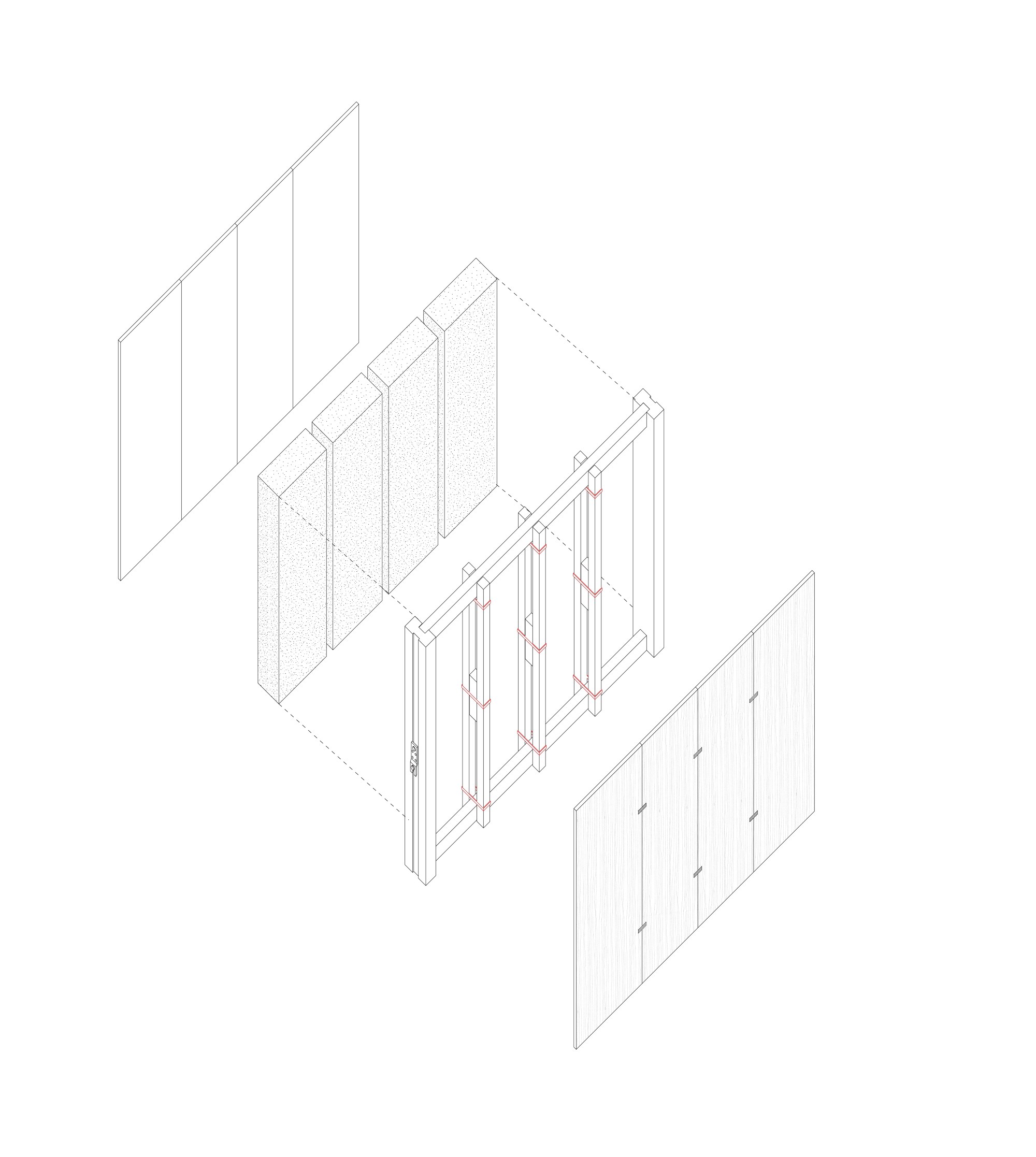
Cassette Panel - Assemblage
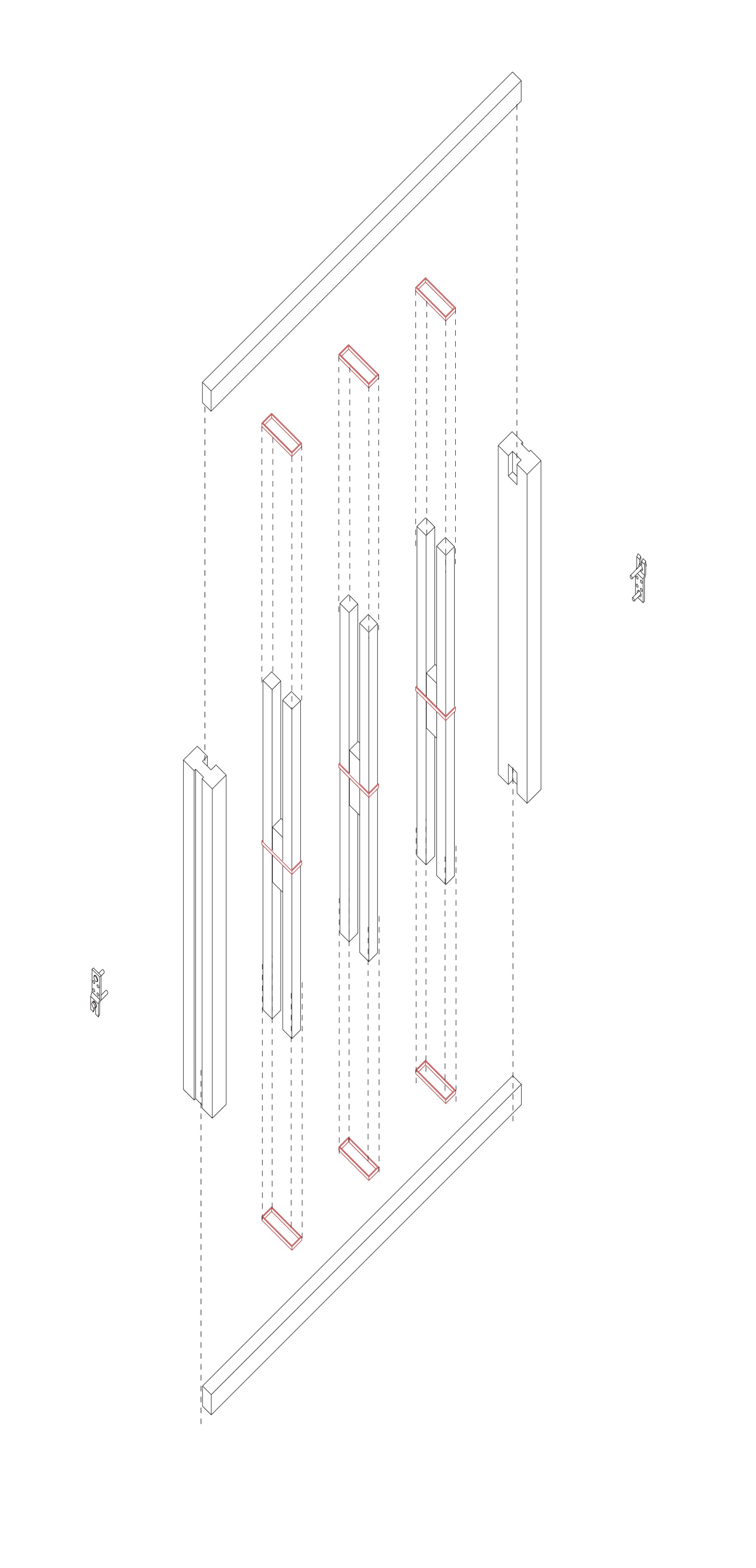
Cassette Panel - Internal Structure
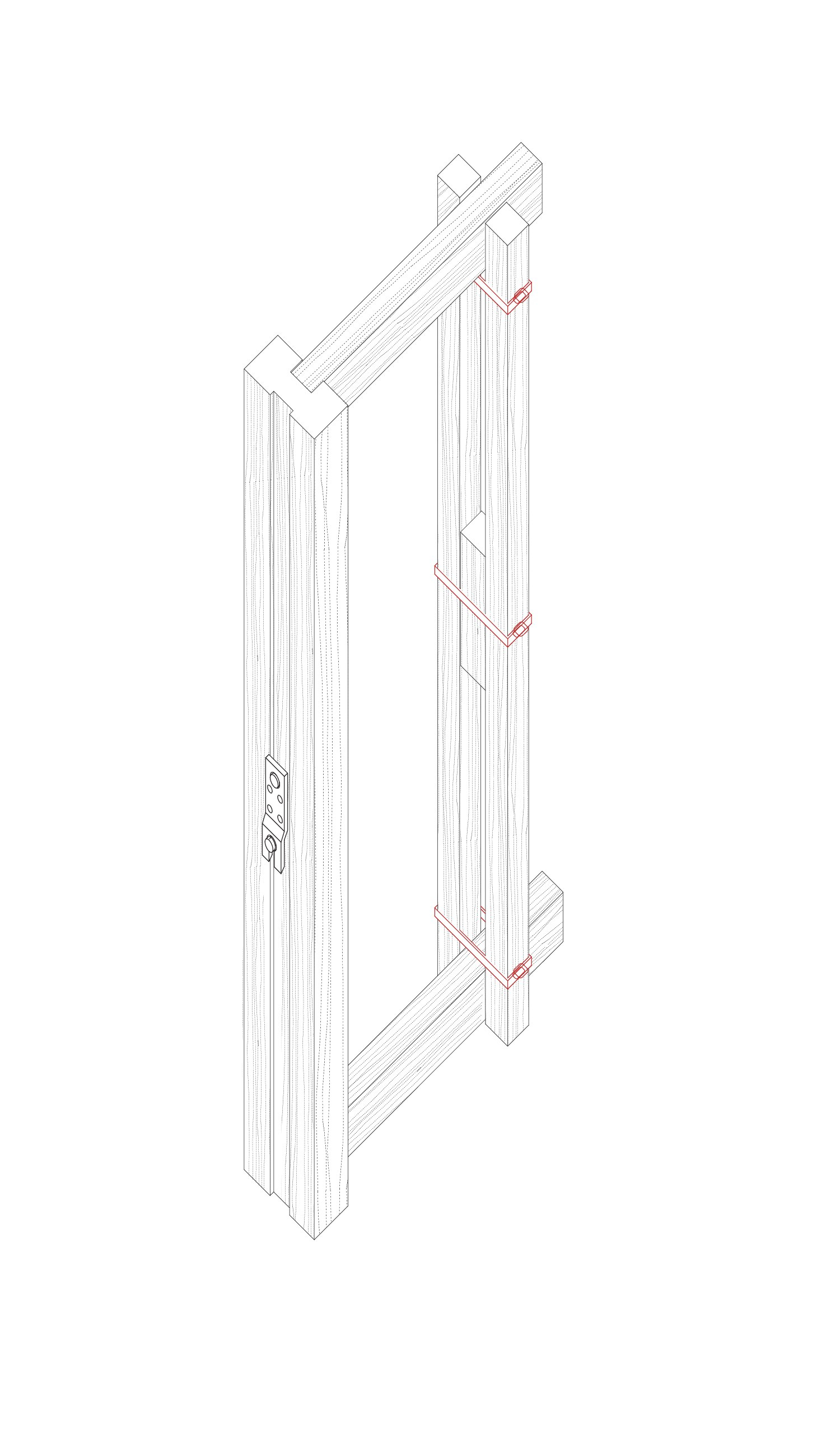
Cassette Panel - Timber assemblage designed for re-assembly + reduced nail fixings
Appendix - Bearing Stone (On Detail)
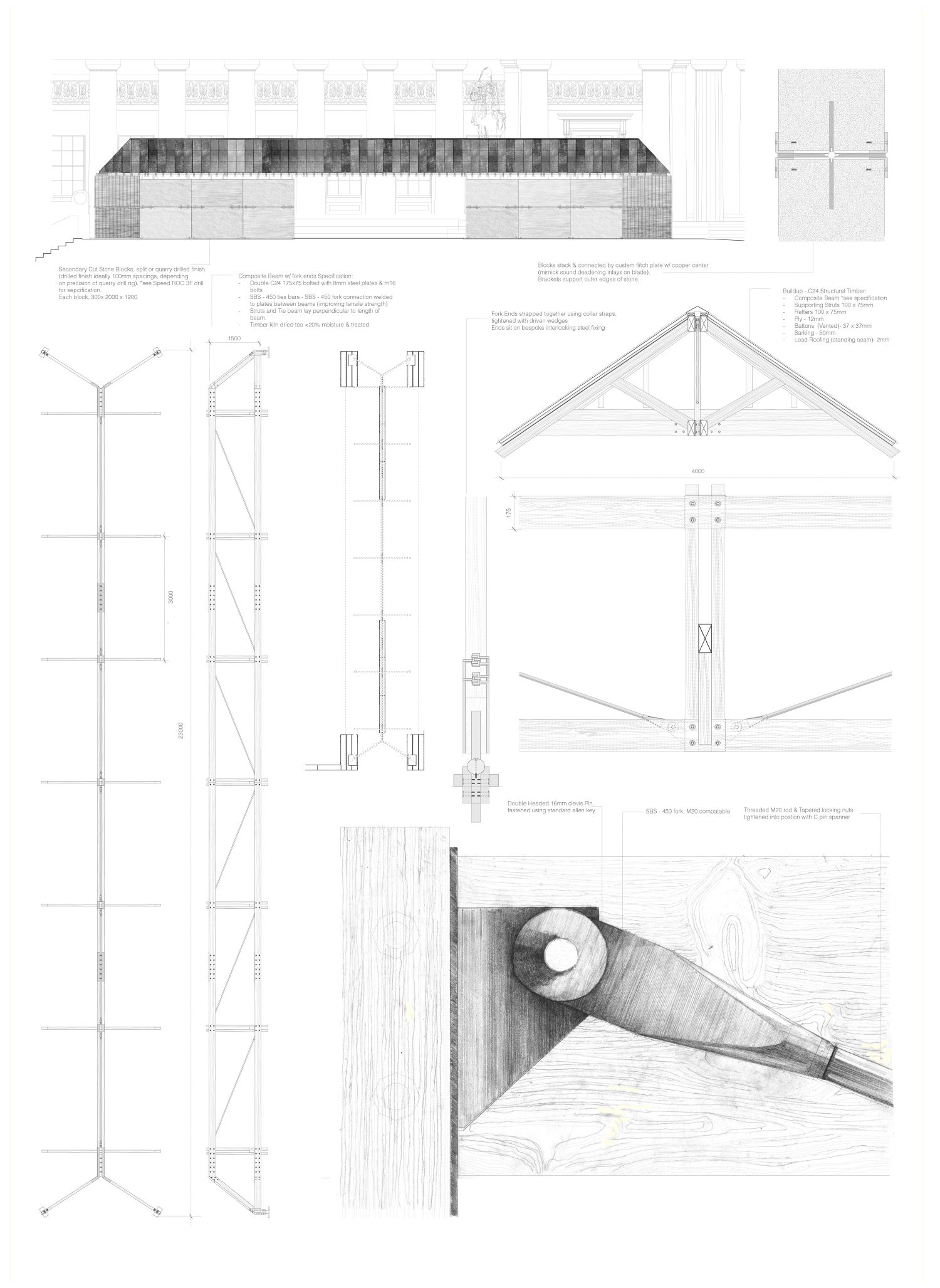
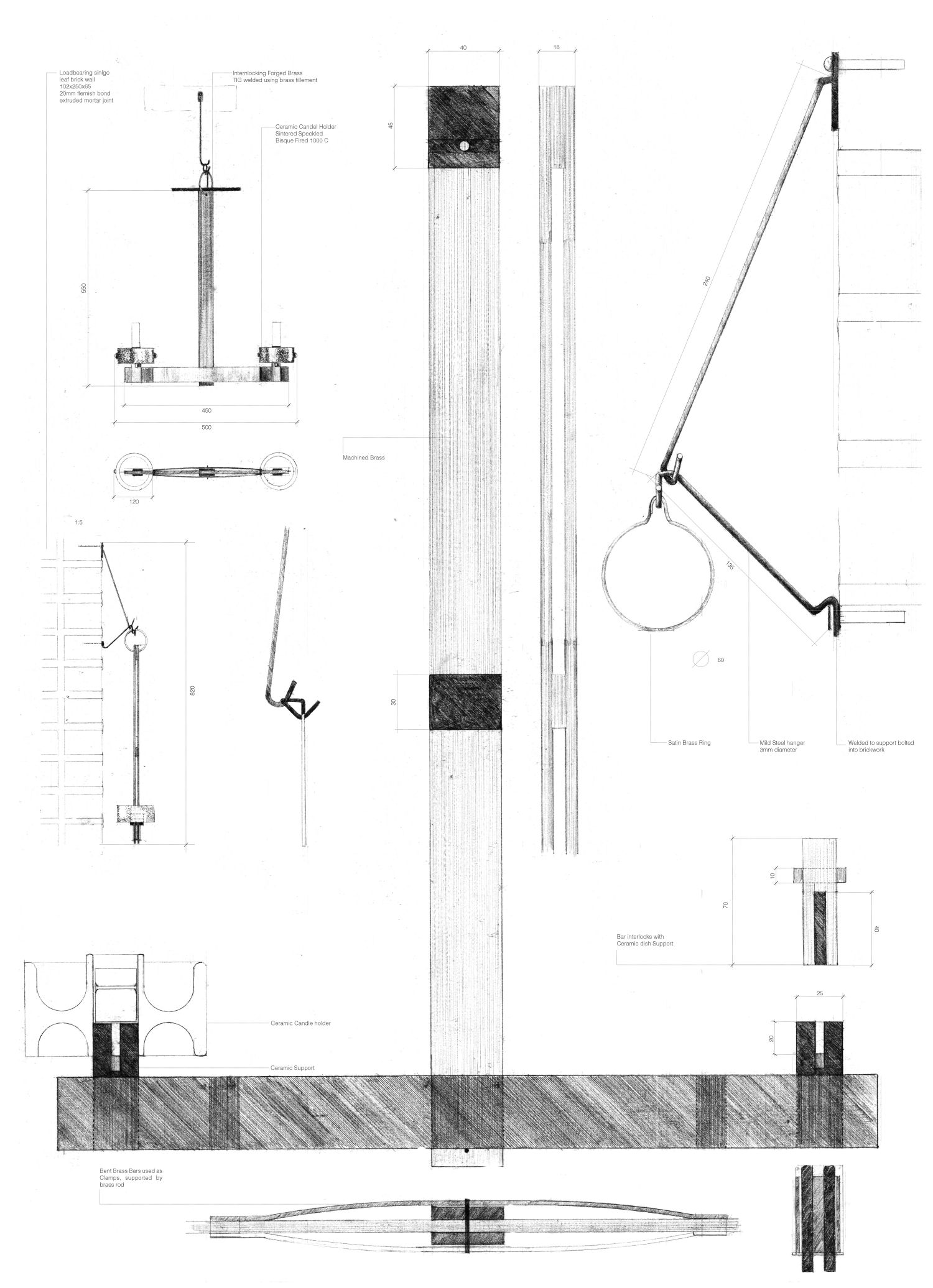
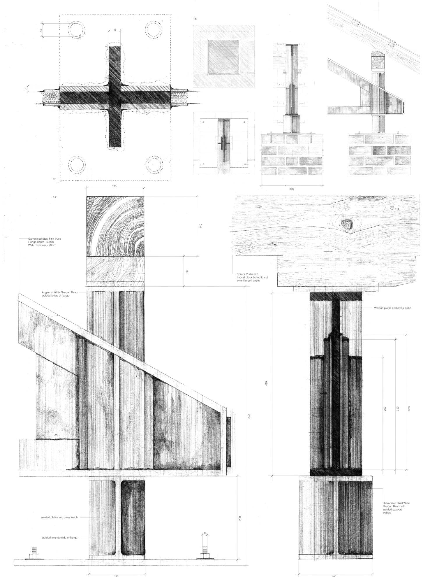
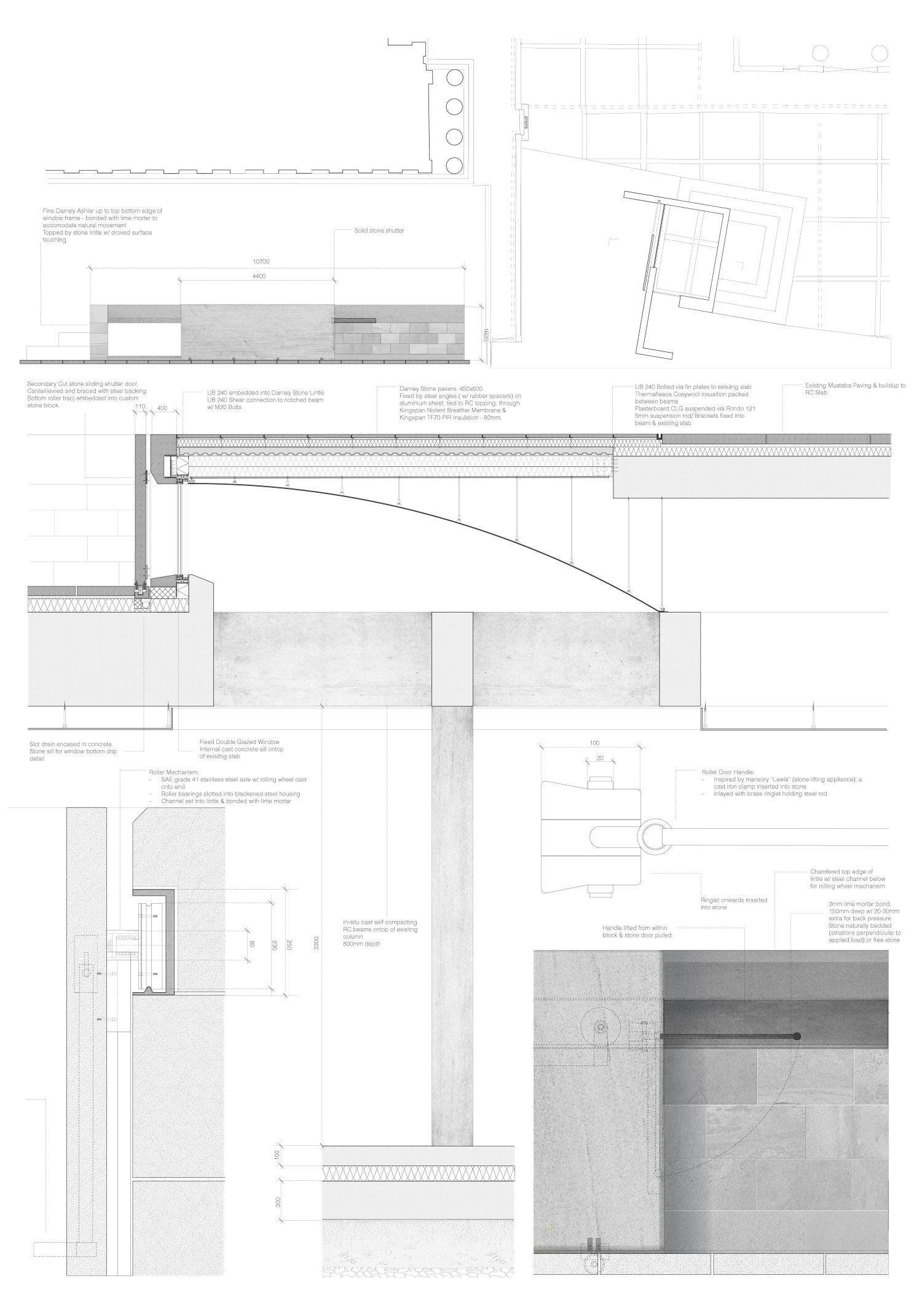
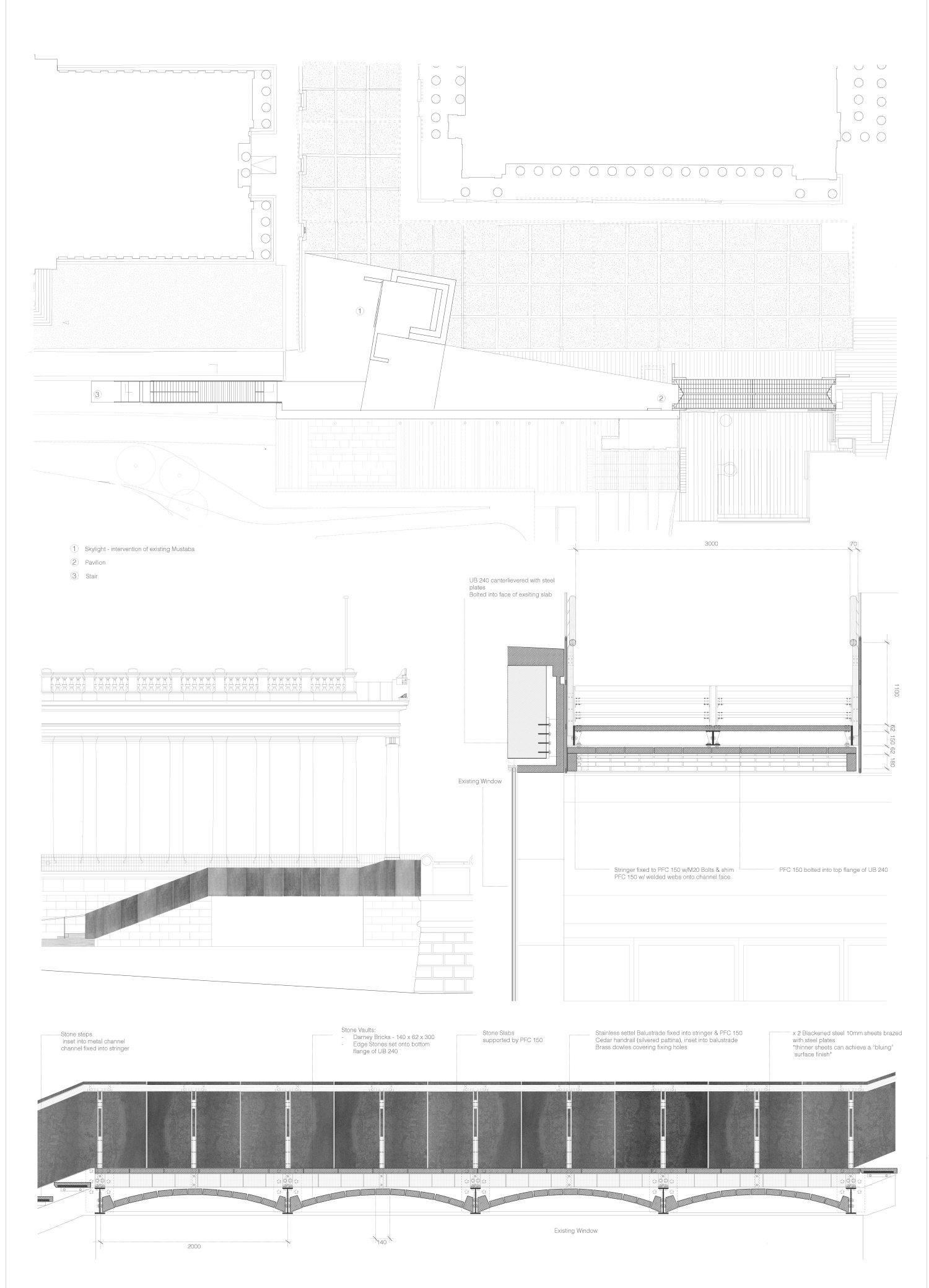
The project encompasses 3 key interventions made on the Plaza between Playfair’s Scottish National Gallery, and the RSA. All structures utilise stone in varying degrees from raw quarried blocks, cut bricks, and fine ashlar pieces. The use of stone as a primary material draws inspiration from visits to the Hutton Stone quarry in Northumberland This degree of refinement is reflected in the typology and overall design of each intervention. From Princes street, individuals are collected via a pavilion like structure, which utilises a timber/steel composite beam, placed upon Secondary cut sandstone blocks, some still with their drill marks visible. From this, the plaza space becomes clearly defined, from that associated with the galleries, and the adjacent area in which, such as the Christmas markets and fringe activities take place. This leads to a skylight, highlighting a deep, crossed concrete beam hidden within the under croft area of the gallery. The skylight sits on an existing “mustaba”, a tomb like object,which is often a place for protest, hence the ability to stand atop of this structure is purposely retained. A sliding stone door allow the viewing platform to be closed for security purposes. A new staircase uses stone bricks to create a Catalan vault like appearance, is significant as this underside is visible from the window directly beneath and provides an additional entrance to the Plaza space between the two galleries.
The project takes inspiration from key precedent studies, particularly drawing on the themes of pragmatic and prosaic characteristics working together to capitalise on the benefits of each property.
Épreuve - Tolerating Pavilion
Épreuve - St Marks Church, Sigurd Lewerentz
Épreuve - Manke House, Heinz Bienefeld
Épreuve - Shuttered Skylight
Épreuve - Bearing Stair, Catalan Vault formed with Darney Bricks

James Langham
A Carved Warren : Reorder, Shell + Lining
Follow:
Share: